
A correct journal diameter does not guarantee that a bearing will sit against its locating face. The corner between those two surfaces, and the dimensions leading to the next shoulder, deserve their own review.
When an assembly stops short of a shoulder, reducing the shaft diameter is an expensive first guess. The bore may already fit correctly. A corner clash, a burr or an incorrect axial dimension can produce an assembly problem that another pass over the journal will not solve.
Our preference at drawing review is to identify the intended contact surfaces first. We want to know where the bearing ring should sit, what holds it from the other side, and which surfaces must remain clear. Then we can discuss how to machine and inspect the part.
Start with the ring that needs to touch the shoulder
A shoulder on the shaft normally locates the bearing's inner ring. Its diameter must provide adequate support without contacting parts that should remain free. The bearing manufacturer's abutment limits help define that envelope. A taller shoulder is not automatically an improvement.
Also show the retention arrangement. A shoulder stops movement toward its face; it does not by itself restrain movement away from that face. Depending on the design, another component, a nut, a retaining feature or the specified fit may provide the opposite restraint. Keep that decision visible on the assembly drawing.
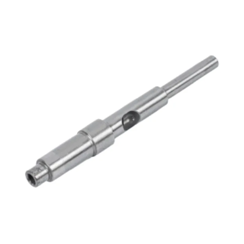
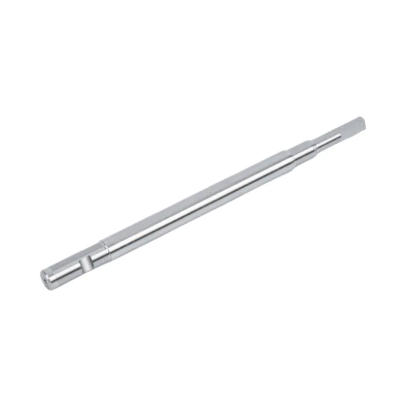
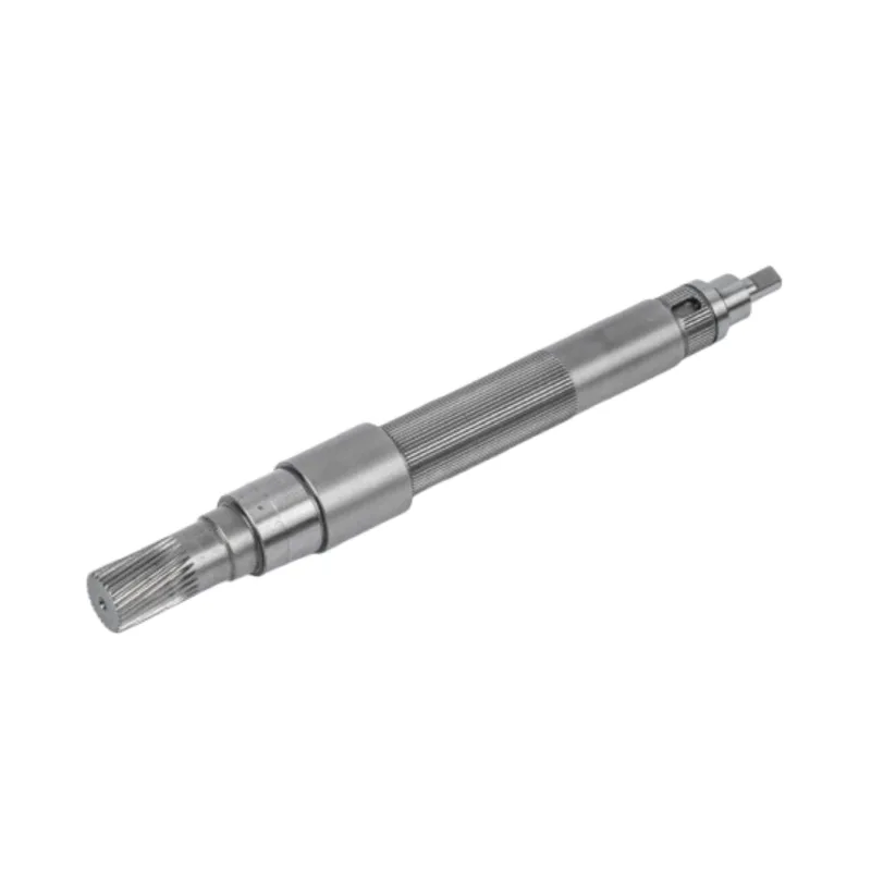
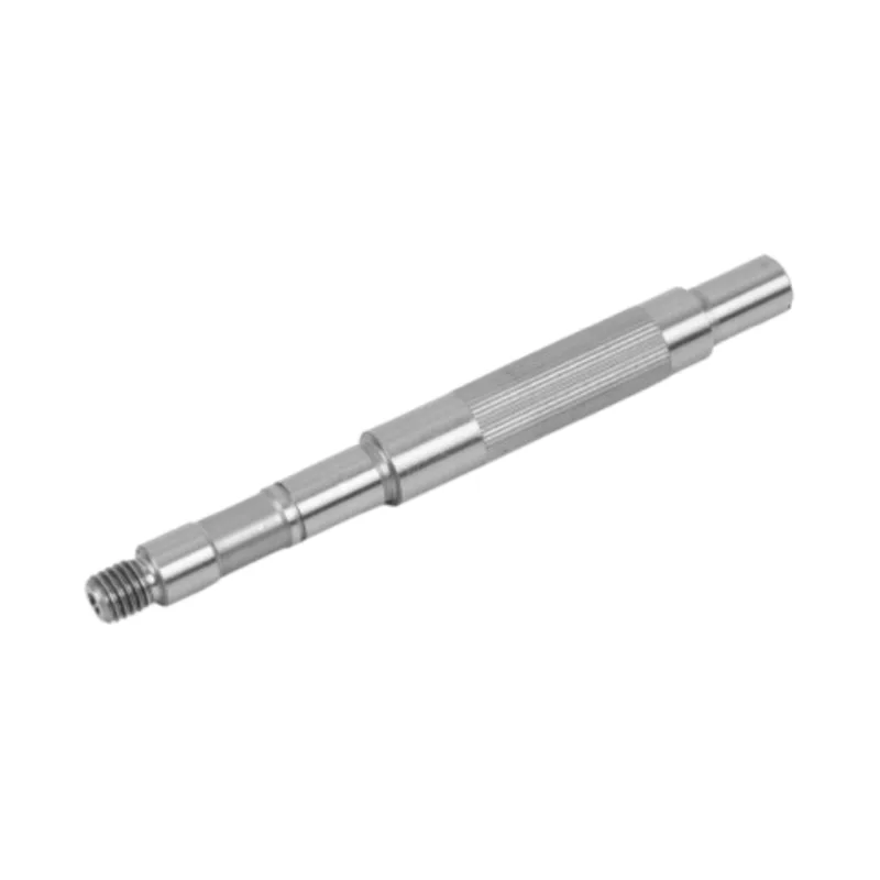
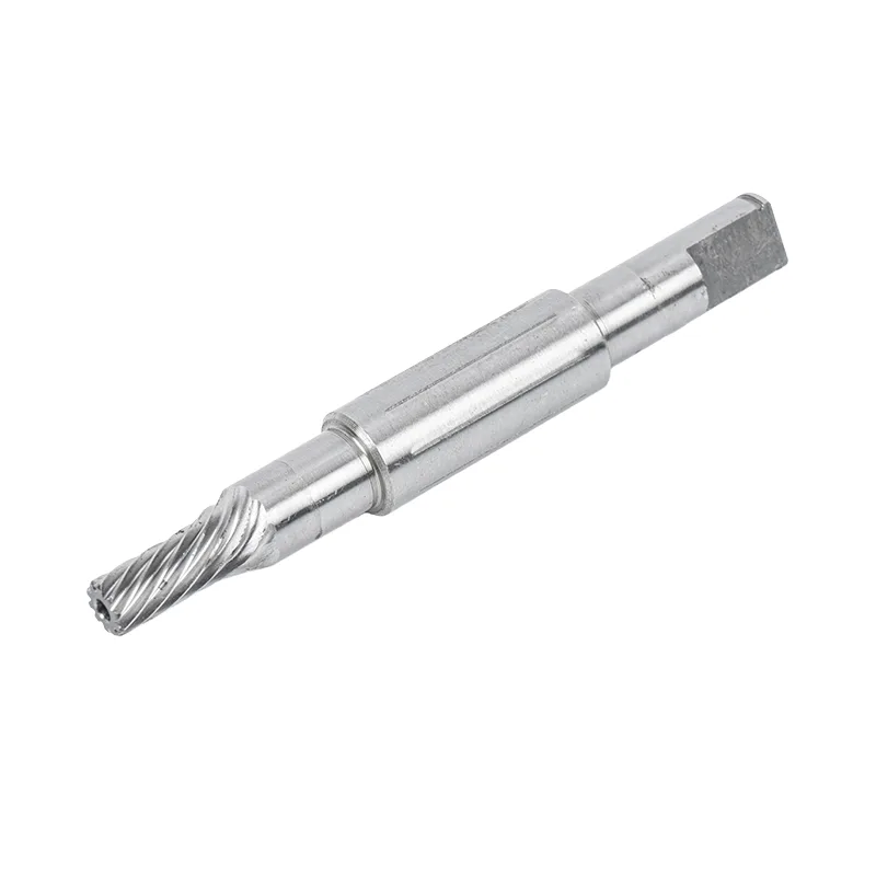
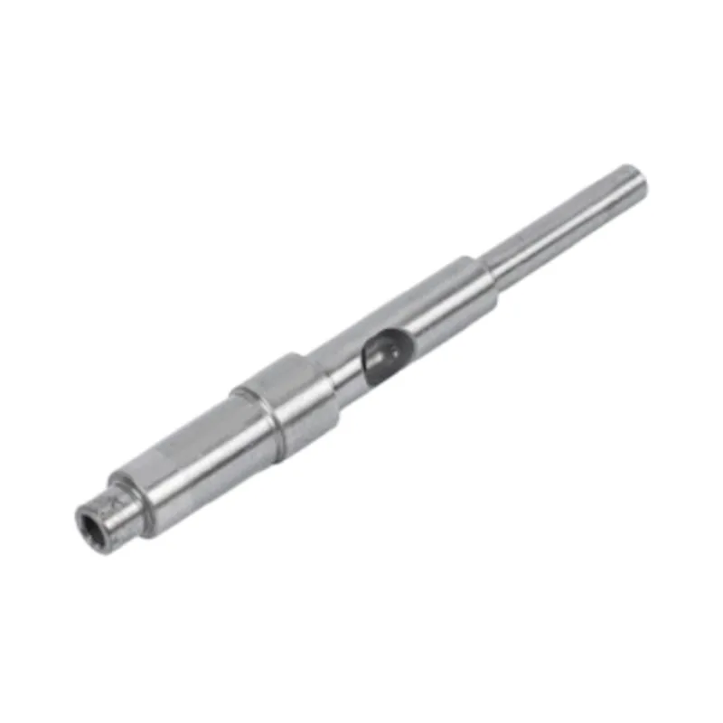
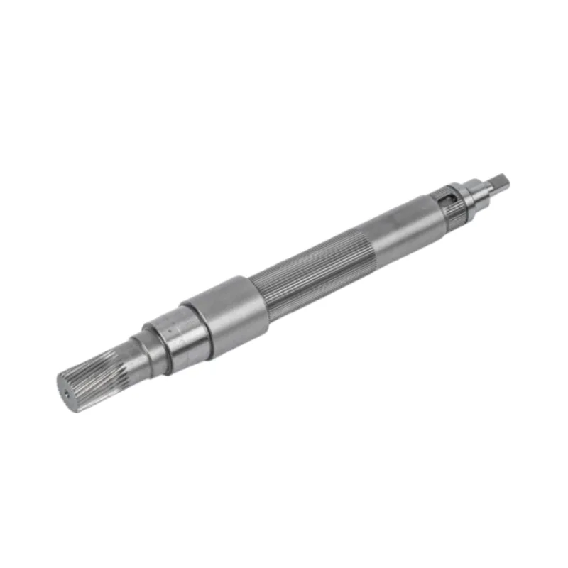
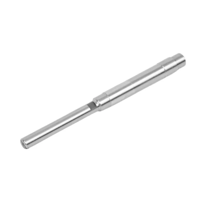
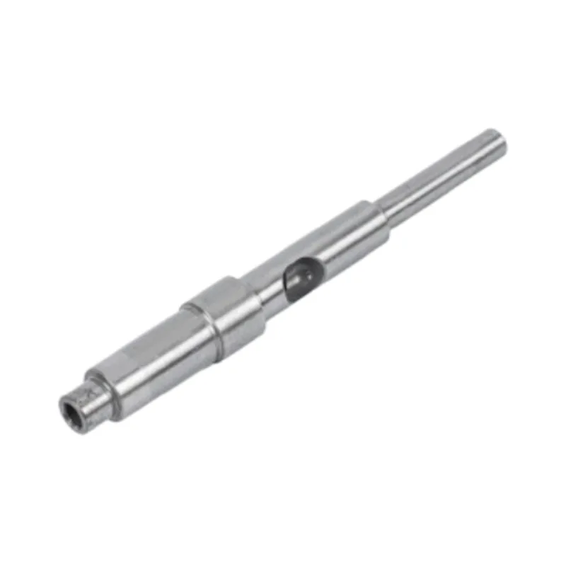
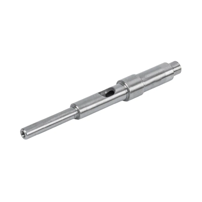
The stepped motor shaft range includes single-step and double-step designs. Selecting between them should follow the number and location of functional interfaces. Adding a step because it looks like a convenient stop also adds a surface and a dimension to manufacture.
A useful fillet must also leave room for the bearing corner
The transition radius occupies space where the journal meets the shoulder. If it intrudes into the bearing ring's corner envelope, the ring can contact the radius before its side face reaches the shoulder. The assembly may look nearly seated while its intended locating face is still unloaded.
Use the exact bearing designation and its recommended shaft fillet and shoulder dimensions. Do not infer the permissible shaft radius from a rounded corner in a catalog picture. A bearing chamfer dimension and the maximum permitted shaft fillet are different drawing entries.
Guanshuo's double-step shaft specification lists a customizable transition radius of R0.5 to R2 mm. That range describes available shaft geometry. It is not permission to use any radius in that range with any bearing.
Choose between a compatible radius and a reviewed relief
For a comparable shoulder geometry, a larger smooth transition generally reduces local stress concentration. That is why simply making the corner sharper deserves a load review. An undercut can provide machining and seating clearance, but it removes material and creates its own local geometry.
If the shaft needs a larger radius than the bearing arrangement accepts, a relieved spacer or a different arrangement may be worth evaluating. Any added spacer also changes the axial dimensions. The shaft designer should review the resulting strength and assembly, rather than treating the spacer as a free fix.
Separate diameter, shoulder orientation and axial location
The official product pages give useful starting points, but the controls describe different things. Keep their names and directions intact when transferring them to an RFQ.
| Published product specification | What it controls | What still needs defining |
|---|---|---|
| Single-step working shaft diameter: g6/h6 | The chosen shaft diameter tolerance zone | Which zone applies, nominal size and the mating bore. This is not a universal bearing-fit recommendation. |
| Single-step shoulder perpendicularity: ≤0.02 mm | Orientation of the step end face | The referenced datum and the actual controlled face |
| Double-step single step width: 3 to 8 mm, tolerance ±0.02 mm | An individual axial step width | The assembled distance that matters and its full tolerance stack |
| Double-step journal radial runout: ≤0.02 mm | Runout of a journal surface | Datum setup and measuring location; this is not an axial face-runout value |
| Double-step transition fillet: R0.5 to R2 mm, customizable | The proposed corner geometry | Compatibility with the mating part and the load case |
Sources: single-step product specifications and the double-step product table linked above. Tables scroll horizontally on small screens.
For a locating shoulder, face orientation and axial position are separate requirements. A face can sit at the correct distance along the shaft and still be tilted relative to the intended axis. It can also be perpendicular but in the wrong axial position. A diameter inspection answers neither question.
Two acceptable step widths can produce an unacceptable total
A drawing with several short, chained dimensions can hide the distance the assembly uses. If a spacer or mounted component spans two of those dimensions, its clearance depends on their sum.
A worked axial stack, with explicit assumptions
Assume two consecutive axial drawing dimensions, A to B and B to C, are each 6.00 ±0.02 mm. The 6 mm nominal is illustrative; the ±0.02 mm is the individual step-width tolerance listed for Guanshuo's double-step product. It is not automatically the tolerance of the combined A-to-C distance.
LAC = LAB + LBC
Minimum: 5.98 + 5.98 = 11.96 mm
Maximum: 6.02 + 6.02 = 12.04 mm
The worst-case total is 12.00 ±0.04 mm. Now suppose an independently specified mating stack spans that distance and measures 11.96 ±0.01 mm. Define the resulting geometric clearance as G = LAC minus the mating-stack length.
| Condition | Calculation | Clearance G |
|---|---|---|
| Nominal | 12.00 − 11.96 | 0.04 mm |
| Minimum clearance | 11.96 − 11.97 | −0.01 mm |
| Maximum clearance | 12.04 − 11.95 | 0.09 mm |
The permitted dimensions can produce geometric interference instead of the positive gap suggested by the nominal values. This is a worst-case arithmetic example, not a prediction of batch distribution or a bearing-preload calculation. It assumes the dimensional extremes can occur together and excludes temperature and elastic deformation.
If A-to-C is the functional requirement, put a suitable control on that distance and plan how to produce it. Replacing chained dimensions with a direct dimension can make the requirement clearer, but it does not improve the process by itself. Avoid conflicting duplicate tolerances; identify any reference dimensions using the drawing convention in use.
We would rather discuss the allowable assembled gap before quoting than discover at sample approval that the buyer intended ±0.02 mm across the whole feature. That is a different requirement from ±0.02 mm on each of two widths.
Show where the tool is allowed to finish
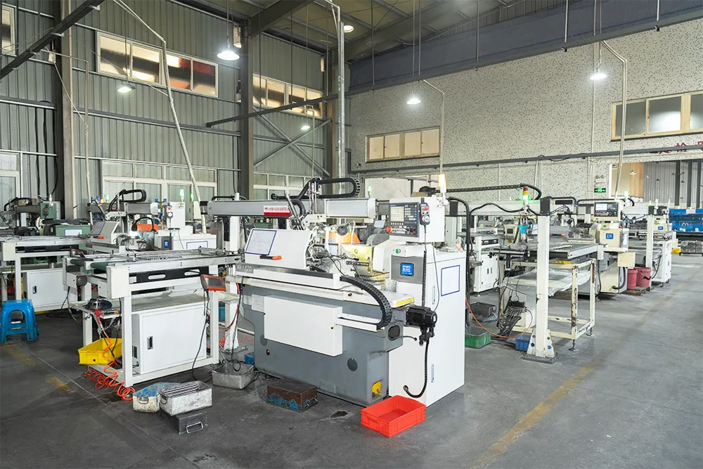
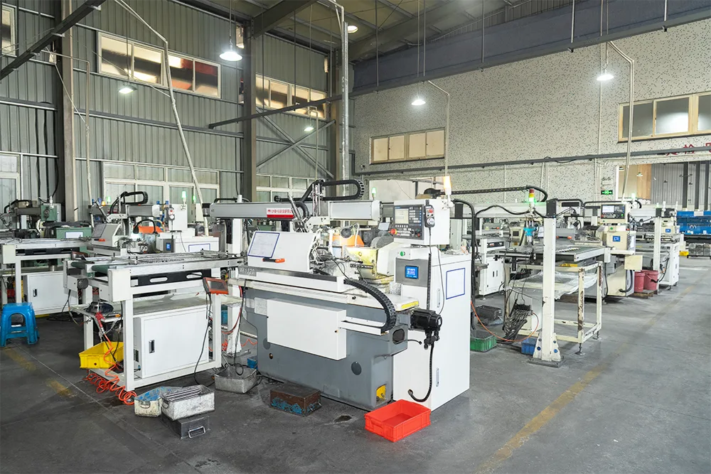
Guanshuo's single-step process can machine the outer diameter, step face and chamfers in one clamping. The product also supports additional precision grinding of the outer surface. Those operations need compatible geometry at the shoulder.
On the drawing, distinguish an entry chamfer from a shoulder fillet. The entry chamfer helps a component start onto the shaft; it does not resolve a clash at the far end of the journal. If the process needs grinding clearance beside a locating face, define the permitted relief instead of leaving a generic "break edges" note to cover the area.
A relief should have an agreed width, depth and transition form. It must leave enough material and usable journal length for the approved design. Do not let an unspecified groove become the supplier's way of making two otherwise incompatible surfaces machinable.
Where heat treatment is required, agree which diameters and faces receive final finishing afterward. The precision shaft machining process explains why final grinding follows heat treatment on the relevant route. A shoulder-to-journal relationship should be checked in the finished condition, not assumed from the earlier turning setup.
When the bearing will not seat, preserve the evidence
Do not immediately polish the journal or grind the shoulder. First record where assembly stops and examine the intended contact region. Changing the part before measuring it can remove the clue that distinguishes a diameter problem from a corner or axial-location problem.
| Observation | Useful check | Decision it supports |
|---|---|---|
| The ring stops close to the shoulder | Compare the shaft transition profile with the mating corner; check for burrs or debris | Determine whether the intended faces can contact before altering the fit |
| The ring does not reach its axial position despite clear corners | Measure the functional shoulder location and actual mating component lengths | Separate an axial stack problem from a seating obstruction |
| Contact varies around the shoulder | Check the face geometry and cleanliness relative to the agreed datum | Identify a face or setup issue rather than calling it journal runout |
| Individual dimensions pass, but assembly clearance fails | Calculate and measure the complete functional stack | Review the drawing's acceptance limits across components |
These observations are investigation prompts, not diagnoses from appearance alone. For inspection, define the journal datum, the shoulder being checked and the instrument setup. Our motor shaft QC report guide explains how to connect the reported value to the drawing requirement.
What we need to review a stepped shaft drawing
- The assembly section and exact bearing or mating-component designation, with its relevant interface dimensions.
- The shaft material, final condition, operating loads and any fatigue-critical locations.
- Journal fits, locating faces and the datums used to relate them.
- The transition radius or relief, including its permissible limits.
- The functional axial distances, required clearance or preload arrangement, and the relevant mating-part tolerances.
- Final surface requirements, inspection method and any observed seating problem.
Send the mating detail with the shaft drawing. It gives us a basis for reviewing the corner, planning the finishing route and agreeing on what the first sample must demonstrate. For the wider choice of shaft form and drive features, use the motor shaft selection guide.
Frequently asked questions
What fillet radius should a stepped motor shaft use?
Choose the radius from the shaft's load requirements and the mating component's permitted corner envelope. Guanshuo lists customizable R0.5 to R2 mm transitions for its double-step shaft, but that product range is not a universal bearing-clearance specification.
Does a shoulder remove the need for axial retention?
A shoulder limits movement toward its face. The assembly still needs an appropriate means of restraint in the opposite direction where the application requires it. Show the complete retention arrangement rather than assuming the shoulder alone locates the part both ways.
Does a ±0.02 mm step-width tolerance apply to the total stepped length?
Not automatically. If two consecutive widths are each controlled to ±0.02 mm, their sum can vary by ±0.04 mm in a worst-case stack. A tighter functional total needs its own agreed dimensional and manufacturing control.
Should a bearing seating problem be corrected by reducing shaft diameter?
Only after inspection identifies the diameter or fit as the cause. A fillet clash, burr, face error or incorrect axial stack can prevent proper seating even when the journal size is acceptable.