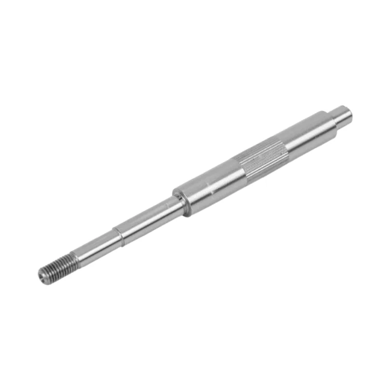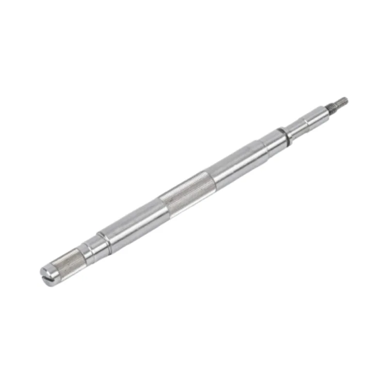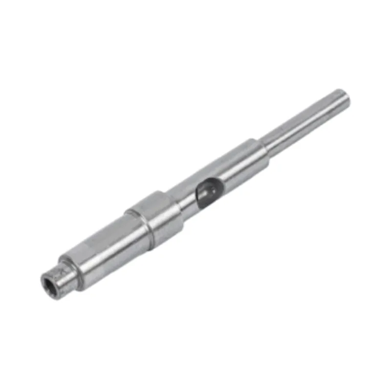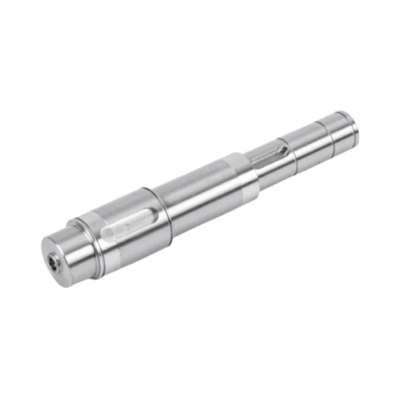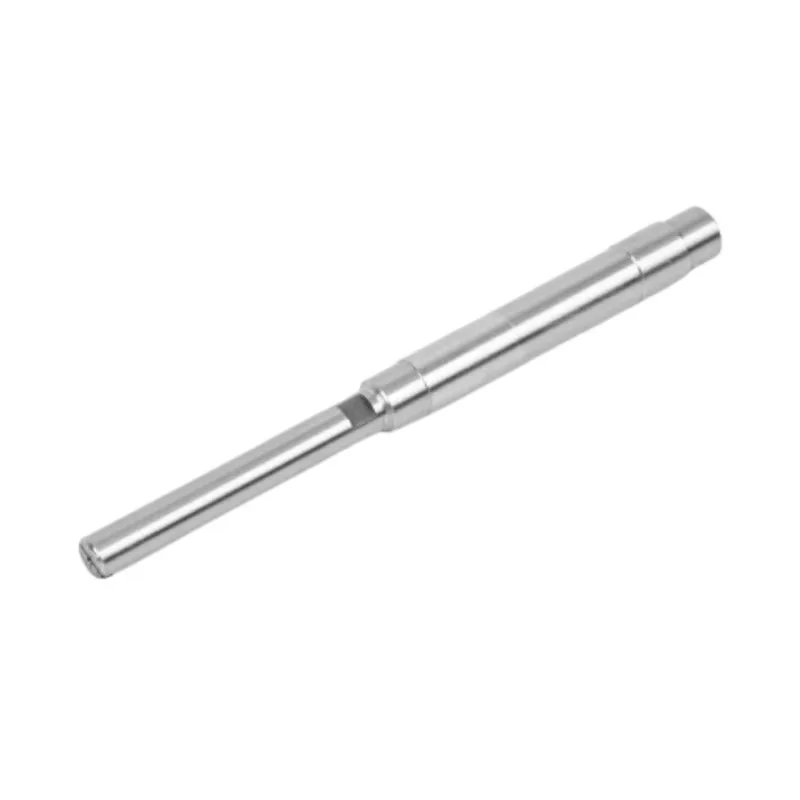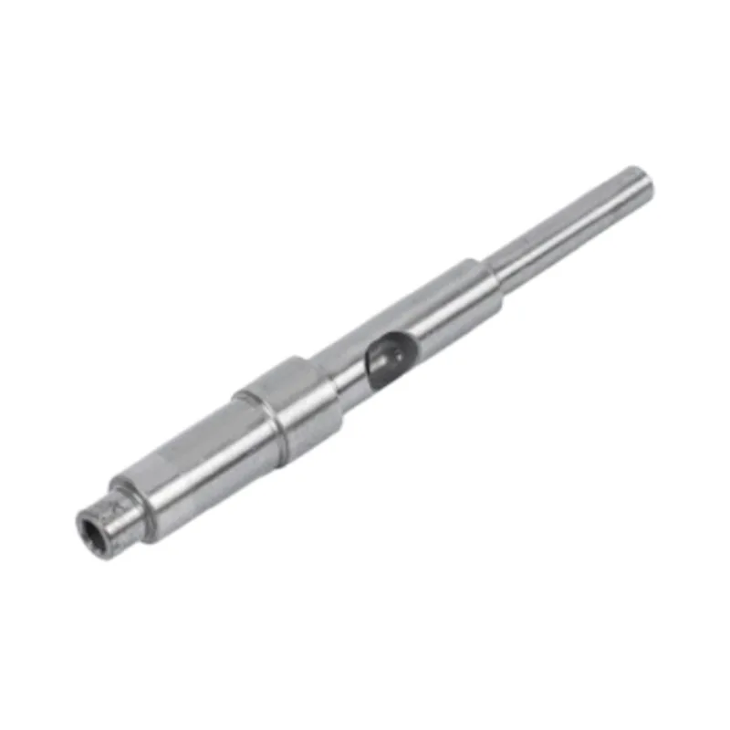

A blind hole can be deep enough on the inspection report and still stop an insert short of its intended position. The missing detail is often the bottom profile: the deepest point of a drilled cavity is not the end of its full-diameter bore.
Our starting point for a drawing review is the component going inside. What locates it? How far must it enter? Does it touch the bottom, or must it stay clear? Those answers determine which dimensions deserve tight control. A precise depth tolerance attached to the wrong feature does not solve the assembly problem.
First, check the bore and depth together
Our blind-hole motor shaft specifications list bore diameters from 2 to 30 mm and hole depths from 5 to 150 mm. The same product page gives a maximum depth-to-diameter ratio of 10:1, with larger ratios requiring engineering review.
That last condition changes how the range should be read. A 2 mm bore and a 150 mm depth are both listed endpoints, but combining them produces a 75:1 hole. It is not a standard combination just because each number appears in the catalogue.
| Bore diameter | Depth used for screening | Depth ÷ diameter | Drawing-review result |
|---|---|---|---|
| 2 mm | 20 mm | 10:1 | At the listed ratio limit; check material, profile, tolerance and inspection access. |
| 10 mm | 100 mm | 10:1 | Passes the ratio screen only. Other requirements still need review. |
| 15 mm | 150 mm | 10:1 | At both the listed depth limit and ratio limit. |
| 2 mm | 150 mm | 75:1 | Outside the listed 10:1 limit; do not treat it as a routine catalogue configuration. |
For a 150 mm screening depth, dividing by 10 gives a 15 mm bore. That is an arithmetic threshold, not a recommendation to enlarge your bore to 15 mm. The larger hole may leave too little wall or change how the insert is retained.
Agree which depth is used in the ratio review. If the drawing specifies full-diameter depth, the drill may have to reach farther to create it. Tool reach, bottom geometry and chip evacuation still belong in the process review.
One hole, three different depths
A note such as BORE 10 × 20 DEEP leaves too much room for interpretation when the last few millimetres matter. Use a section view and identify the controlled surfaces.
Full-diameter depth
This is the axial reach of the specified cylindrical bore before the bottom profile begins to reduce its diameter. If an insert needs a defined length of cylindrical engagement, dimension that region. A lead-in chamfer at the mouth does not provide the same contact as the straight bore.
Deepest-point depth
This reaches the furthest internal point. With a conical drill bottom it extends beyond the full-diameter region. It matters when checking the remaining material at the closed end, but it does not tell you how far a flat-ended insert can enter.
Usable installation length
This belongs to the assembly, not to the drill. It depends on the mating part's diameter and end shape, its locating shoulder, the mouth chamfer and any required bottom clearance. A smaller or chamfered insert may enter part of a tapered bottom; a close-fitting, flat-ended insert may not. Check the mating profiles together.
Our factory view: if the insert must seat on a shoulder, make that shoulder the locating feature and define clearance to the hole bottom. If the bottom must locate the insert, specify its contact geometry and the relevant depth from the assembly datum. Do not leave that choice to a generic drilling note.
A requirement for a flat bottom also needs detail. State the required bearing area, allowable corner radius and whether a central recess is permitted. A tool described as a flat-bottom drill does not, by its name alone, define every feature left in the cavity.
Calculate the end wall at the worst permitted dimensions
The nominal distance left behind the bore is not the minimum wall. Use the shortest permitted outside length and the deepest permitted internal feature, both referenced from the same face.
If the 20.00 mm dimension instead controlled the deepest point, the same outside length would give 24.95 − 20.02 = 4.93 mm. The 3 mm difference comes entirely from the meaning of the depth dimension. Tightening ±0.02 mm would not resolve that ambiguity.
This calculation checks geometry only. It does not establish that a 1.93 mm wall is safe under torque, bending, insertion load, internal pressure or fatigue. Material, heat treatment and the complete shaft geometry still need design assessment.
Check radial wall separately. For a centred, round bore in a round shaft section, nominal radial wall is (outside diameter − bore diameter) / 2. An offset bore leaves a thinner wall on one side. Review the bore against the smallest surrounding shaft section and nearby grooves or cross-holes, not just the largest outside diameter.
Put precision where the assembly needs it
Guanshuo's blind-hole product data lists bore diameter tolerance of ±0.01 mm, depth tolerance of ±0.02 mm, bore-to-journal coaxiality of ≤0.01 mm and bore inner-wall roughness of Ra ≤0.8 μm. These are different controls. None substitutes for the others.
| Listed blind-hole parameter | What it helps control | What the drawing still needs |
|---|---|---|
| Bore diameter ±0.01 mm | Permitted bore size | Mating-part limits and intended clearance or interference; identify the controlled bore region. |
| Depth ±0.02 mm | Axial position of the specified depth feature | Reference face and whether the dimension ends at the cylinder, seating face or deepest point. |
| Bore-to-journal coaxiality ≤0.01 mm | Relationship of internal and external features | Functional journal datum, applicable drawing standard and agreed verification method. Do not relabel this as surface runout. |
| Inner wall Ra ≤0.8 μm | Bore surface texture | Surface region, evaluation requirements and access for measurement. It does not specify diameter or bottom flatness. |
For a clearance example, a 10.00 ±0.01 mm bore and a 9.97 ±0.01 mm insert give a minimum diametral clearance of 9.99 − 9.98 = 0.01 mm and a maximum of 10.01 − 9.96 = 0.05 mm. These are illustrative limits, not a recommended fit. Whether they work depends on temperature, retention, alignment and assembly requirements.
We would rather review those two mating dimensions together than add a tighter bore tolerance without a reason. If only a short region locates the insert, identify that region. The rest of the cavity may serve as clearance space, subject to the design.
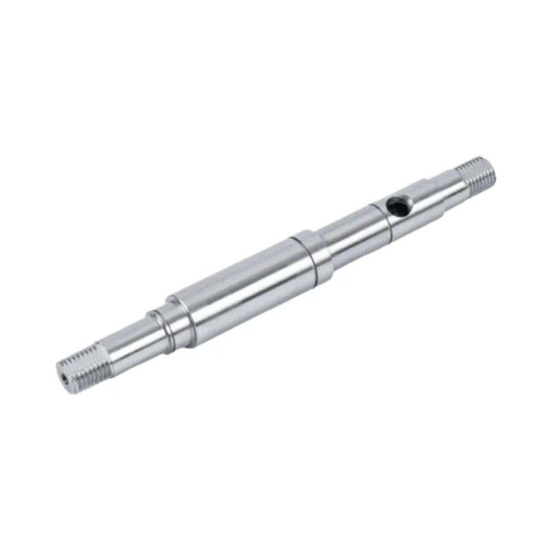
A blind cavity suits a component that enters from one end while the other end remains closed. A through-hole motor shaft suits a continuous passage. Do not choose a blind hole for a cable or fluid route that must exit the opposite end unless the design includes another suitable passage. A closed end alone also does not establish a sealed assembly or an ingress-protection rating.
The closed end changes machining and inspection
Guanshuo uses CNC turning and boring for its blind-hole shafts. From a manufacturing perspective, the difficult question is not simply whether a cutting tool can reach the depth. Chips must leave the hole without damaging its surface, the tool must remain stable, and the finished geometry must be measurable.
Longer reach and restricted access make the material and chip-evacuation strategy important. A drawing that adds internal grooves, a tight bore fit and a controlled bottom face may require a different sequence from a plain clearance cavity. Identify which features perform a function before asking for the same finish everywhere.
At inspection, measuring the mouth does not establish bore size throughout the engagement length. Likewise, a depth probe touching the cone cannot establish full-diameter depth unless its contact geometry and measurement method account for that profile.
| Requirement | Agree with the manufacturer |
|---|---|
| Insert engagement | Where bore size is checked and how the usable cylindrical length is verified. |
| Bottom clearance or seating | Which surface the depth measurement contacts, and how bottom profile is verified. |
| Alignment to the shaft | Which working journal establishes the datum and whether the inspection method reaches the required internal region. |
| Cleanliness | Permitted residual chips or contamination, inspection access, and protection after cleaning. Use an application-specific acceptance criterion. |
| Final condition | Whether size, geometry and roughness apply after heat treatment and any final surface process. |
A functional gauge can help check a defined mating envelope, but it does not automatically prove every size, texture and geometric requirement. Choose the measurement method for the characteristic being accepted. Our motor shaft inspection guide covers the wider shaft checks; the blind cavity needs its own access and contact-point review.
Send the mating detail, not just the hole diameter
For a useful quotation review, send the shaft section together with the insert drawing or its relevant dimensions. Guanshuo's blind-hole customization process accepts the internal component's drawing or a physical sample. Include:
- The cavity's purpose and the feature that locates or retains the internal component.
- Bore size limits, required engagement length, bottom clearance or seating requirement, and permitted bottom profile.
- Minimum end and radial walls, plus nearby threads, grooves or cross-holes.
- Material, heat-treatment condition, final surface requirements and functional journal datums.
- Inspection and cleanliness acceptance criteria, with the mating-part limits where fit matters.
The most useful drawing improvement is often a section view with one unambiguous depth reference. It lets design, machining and inspection work toward the same assembly condition.
Frequently asked questions
Does a 20 mm blind-hole depth mean an insert can enter 20 mm?
Not necessarily. The dimension may refer to the deepest drill point rather than the full-diameter bore. Usable installation length also depends on the insert's diameter, end profile, locating feature and required clearance.
Can Guanshuo make a 2 mm bore 150 mm deep within its listed range?
That combination gives a 75:1 depth-to-diameter ratio, outside the listed 10:1 limit. The separate 2-30 mm diameter and 5-150 mm depth ranges do not approve every combination. Larger ratios require engineering review.
How do I calculate the minimum blind-hole end wall?
Subtract the maximum deepest-point depth from the minimum opening-face-to-closed-end length, using the same reference face. If depth is specified to the full-diameter region, include the maximum additional bottom-profile depth. The result is a geometric clearance, not a strength approval.
Should every blind-hole motor shaft have a flat bottom?
No. Specify a controlled bottom seating surface when the assembly needs it. If the insert locates elsewhere and clears the bottom, an allowed drill-bottom profile may be sufficient. Define any required contact area, corner radius and central-recess allowance.
Does Ra ≤0.8 μm describe the blind-hole inner wall?
Yes. Guanshuo's blind-hole product specification lists Ra ≤0.8 μm for the inner wall. State the required surface region and inspection conditions on the drawing; the roughness value does not establish bore fit, alignment or bottom flatness.