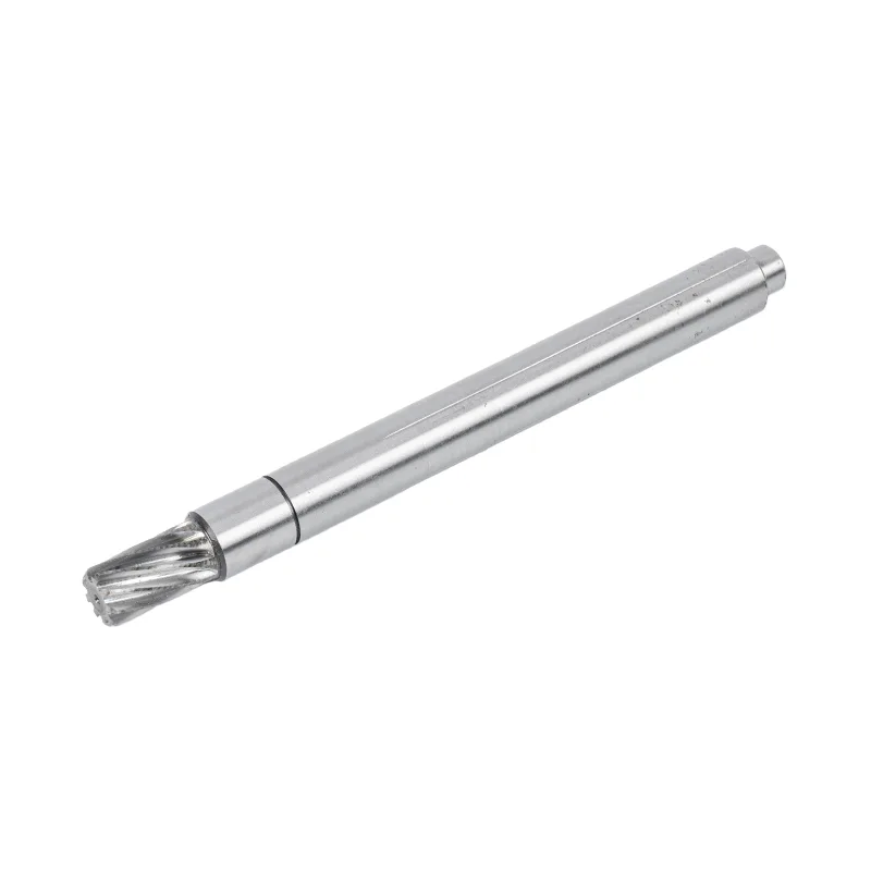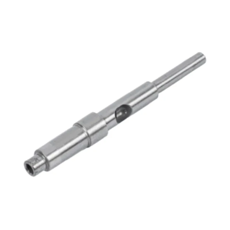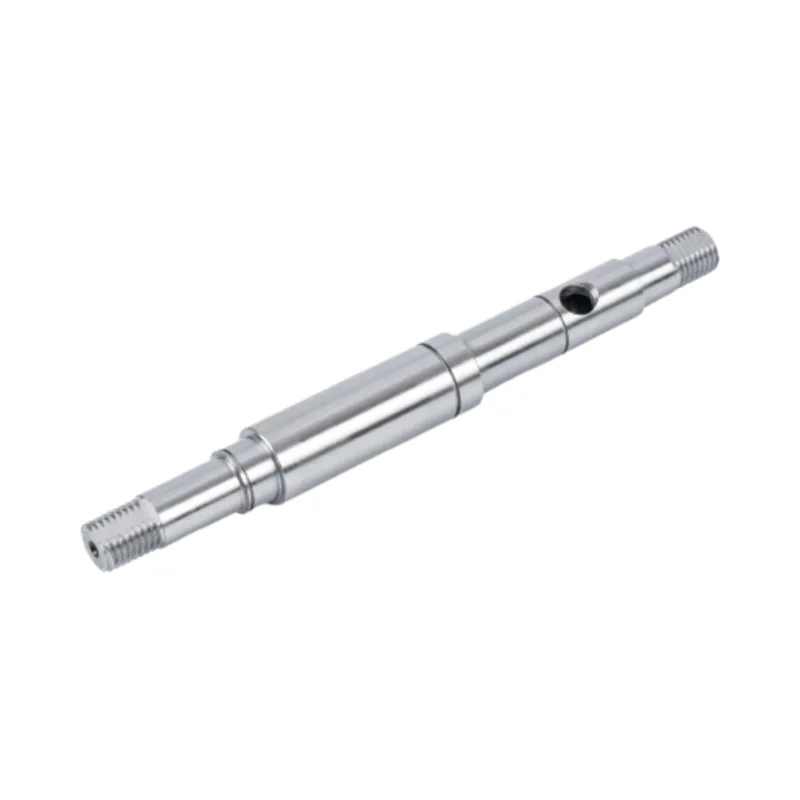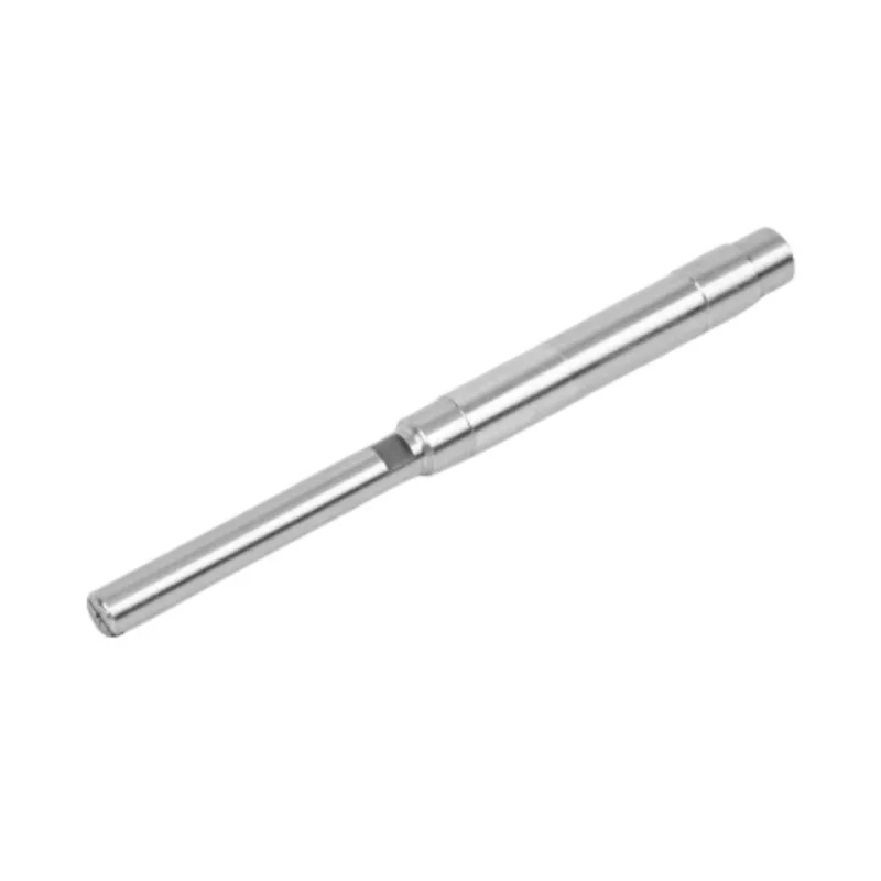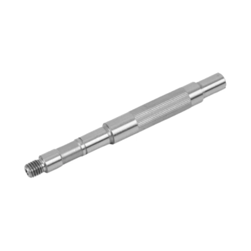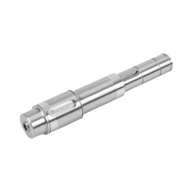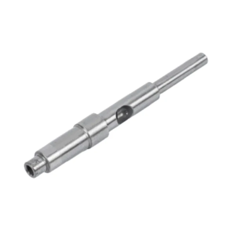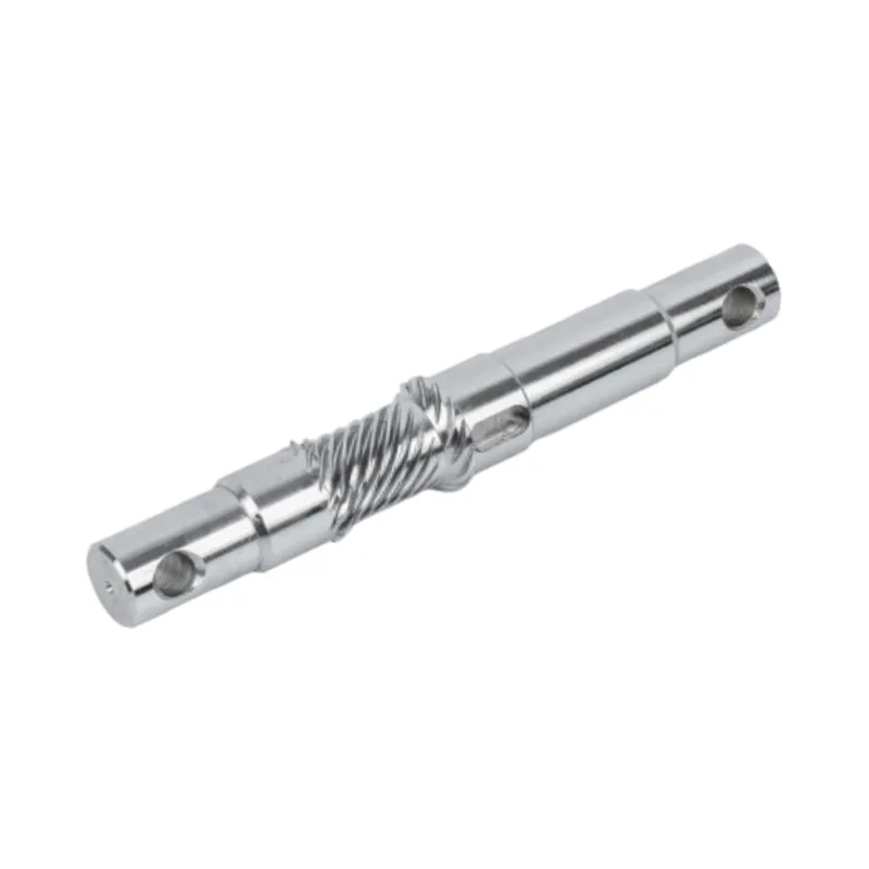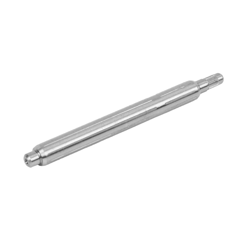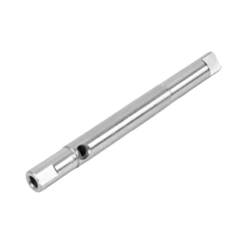

Putting the lowest Ra value in the general notes may look safe. In practice, it can hide the surfaces that matter and make the whole shaft more expensive. A better drawing assigns finish by what each journal, land and drive feature actually does.
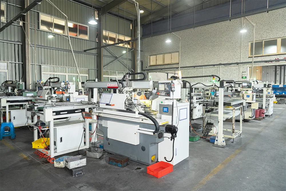
Specify motor shaft surface roughness separately for each functional zone. Mark the bearing journals, seal contact lands, rotor or press-fit seats and torque-transfer features on the drawing, then give each zone the finish its mating part requires. Keep diameter, runout, straightness and cylindricity as separate controls. At Guanshuo, published finishes range from Ra ≤ 0.8 μm on one stainless smooth-shaft product to Ra 0.2–0.4 μm on a high-speed shaft and Ra 0.05–0.2 μm on the bearing position of an ultra-precision shaft. Those are product-specific ranges, not one blanket specification for every motor shaft.
A surface roughness symbol is small, but it can change the entire production route. It may turn a diameter that could be finished on a lathe into a grinding operation. It may also add polishing, another inspection characteristic and extra handling to protect the surface.
That cost is justified when the surface carries a bearing, runs under a seal or controls a precision fit. It adds little value on a clearance section that touches nothing. The drawing should make that difference obvious.
Why one Ra value for the whole shaft is usually the wrong instruction
We often see a general finish note placed in the corner of a drawing, while the shaft itself has four or five different jobs along its length. The note is easy to read but hard to manufacture sensibly. Does it apply to the bearing seats only? Does it include the keyway floor? Is the thread crest expected to meet the same value? What about a relief groove that exists only for tool clearance?
If the answer is “everywhere,” the factory may have to protect and finish surfaces that do not affect the assembly. If the answer is “only where needed,” the drawing has not told the inspector where to measure.
The most expensive roughness callout is not always the smallest number. It is the number with an unclear boundary. Before we choose a wheel, polishing pass or inspection plan, we want to know where the requirement starts, where it stops and which mating component made it necessary.
A better approach is to treat surface finish as a local functional requirement. The shaft can still carry a general finish for non-critical machined areas, but the important zones receive their own leader, length and Ra value.
Map the shaft by functional surface
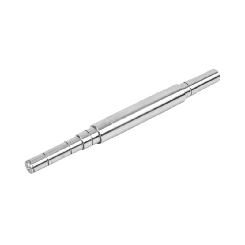
A motor shaft is not one surface. Read from left to right, it may contain a coupling end, a bearing journal, a seal land, a rotor seat, another bearing journal and a non-functional extension. Each zone sees a different contact condition.
Functional surface map for a stepped motor shaft
This map is a specification method, not a universal shaft design. The final zones and values must follow the mating parts and operating conditions in the actual assembly.
Bearing journals
A bearing journal needs the correct diameter fit and a surface that supports consistent contact. Roughness matters, but a polished journal with the wrong diameter or excessive runout is still a bad bearing seat. Put the Ra callout beside the journal and keep its fit and geometric controls visible.
Seal contact lands
The seal supplier's requirement should lead here. Identify the exact contact width rather than applying the finish to the nearest full diameter. Where the seal design controls surface direction or additional texture characteristics, put those requirements on the drawing too. Ra alone does not describe the direction of machining marks.
Rotor, gear, pulley and coupling seats
These interfaces often depend on fit, torque transfer and alignment. A low Ra may support assembly, but it does not prove coaxiality or prevent a wrong press fit. Start from how the component is located and loaded, then decide how much finish is actually needed.
Keyways and spline flanks
On drive features, profile, position and load distribution can matter more than making the surface visually bright. Guanshuo's current process article, for example, gives Ra ≤ 0.8–1.6 μm for involute spline tooth flanks, together with separate symmetry and division-error controls. That is the right pattern: finish and geometry are related, but they are not interchangeable.
What Guanshuo currently publishes across its shaft pages
Our own website shows why one “standard motor shaft Ra” is not a useful answer. Different product pages publish different finish levels because their applications and precision classes differ. The table below brings those scattered values into one view.
| Current Guanshuo page | Published surface roughness | Related published controls | How to read the value |
|---|---|---|---|
| Stainless steel smooth motor shaft | Ra ≤ 0.8 μm | Straightness ≤ 0.03 mm; coaxiality ≤ 0.02 mm; circularity ≤ 0.01 mm; cylindricity ≤ 0.02 mm | A product-level specification for this stainless smooth-shaft page, not a default for all stainless parts. |
| Precision grinding of smooth motor shafts | Ra ≤ 0.4 μm | IT5–IT6 dimensional accuracy; straightness ≤ 0.01 mm | A published precision-ground smooth-shaft capability tied to grinding and inspection. |
| Stepped motor shaft | Often Ra 0.4 μm or lower on key bearing and sealing surfaces | Page emphasis is on multi-diameter mounting and feature relationships | The wording is local: critical bearing and seal zones receive the fine finish, not automatically the entire stepped shaft. |
| High-speed motor shaft | Ra 0.2–0.4 μm | Outside diameter h6 / h5; shaft runout ≤ 0.001–0.003 mm | A high-speed product range where finish is paired with a tight running geometry. |
| Ultra-precision motor shaft | Ra 0.05–0.2 μm at the bearing position | Outside diameter h5; coaxiality ≤ 0.002 mm; radial runout ≤ 0.003 mm | The tightest published range in this comparison. It is explicitly scoped to the bearing position of the ultra-precision product. |
It is that roughness belongs to a product class and a functional surface. Copying Ra 0.05–0.2 μm from an ultra-precision bearing position onto an ordinary clearance diameter would change the process and inspection burden without proving a benefit in the assembly.
What Ra controls, and what it cannot control
Ra is the arithmetic average of the height deviations in a measured surface profile. It is useful because it reduces a complex trace to a comparable number. That convenience is also its weakness. Two surfaces can share one Ra value while having different peak shapes, spacing or machining-mark direction.
For a motor shaft drawing, think of Ra as one member of a control set. It describes fine texture. It does not tell us whether the diameter is correct, whether the journal is round or whether two bearing seats rotate about the same axis.
| Control | Question it answers | What it does not prove | Factory check |
|---|---|---|---|
| Surface roughness (Ra) | How large are the average fine profile deviations? | Diameter, roundness, lay direction or alignment to another journal | Surface roughness tester at the defined zone |
| Diameter and fit | Will the shaft assemble with the mating bore as intended? | Whether the surface rotates true to the working axis | Size measurement with equipment suited to the tolerance |
| Roundness / cylindricity | Is the journal form round and consistent along its length? | Its relationship to a remote bearing or drive feature | Cylindricity measurement |
| Runout | How much does the controlled surface vary while rotating about a datum axis? | The microscopic surface texture | Rotational measurement to the drawing datum |
| Straightness | Does the shaft or its derived line stay within the permitted straightness zone? | Local roughness or the final mating fit | Method chosen for the specified feature and tolerance |
This distinction prevents a common purchasing mistake: approving a shiny sample while the feature relationship is wrong. Appearance can be useful, but the drawing and inspection results have to describe the function.
A factory workflow for setting the drawing
When the Ra value is not yet settled, we would not start by opening a finish chart. We would start with the assembly. The sequence below turns a vague request for a “smooth shaft” into requirements that production and inspection can both follow.
From mating component to measurable finish
The order matters. A finish target without a defined functional zone or measurement point is still incomplete.
1. Mark what touches the shaft
List the mating part on each diameter. A bearing inner ring, dynamic seal, rotor stack and free clearance area do not ask the same thing from the metal. If the mating part is not known, mark the requirement for review rather than borrowing the smallest Ra elsewhere on the drawing.
2. Establish the working axis and fit
Choose the datum that represents how the shaft rotates in the motor. Then control the critical journals to that axis. This is where diameter tolerance, runout and cylindricity enter the drawing. Roughness should support those requirements, not stand in for them.
3. Apply Ra to a bounded length
Show the exact journal or contact land. On a stepped shaft, a leader can point to one diameter with a defined length. For a short seal track inside a longer ground diameter, identify the seal contact zone separately if its finish requirement differs.
4. Review the process before freezing the value
The practical question is whether the specified material, hardness, geometry and quantity can follow a stable finishing route. If the shaft is heat treated, finish grinding normally follows hardening so it can remove the movement caused by heat treatment and establish final size and surface.
5. Make acceptance unambiguous
Decide where the roughness trace will be taken and what documentation the order needs. A supplier and buyer should not discover at final inspection that they interpreted the measurement zone differently.
Match the finish to a realistic process route
Surface finish does not come from one machine setting in isolation. Material condition, turning allowance, heat treatment movement, grinding setup, wheel condition, coolant and handling all affect the final surface. The tighter the target, the more the whole route has to support it.
Our precision shaft machining process places grinding after heat treatment. That order allows the final operation to correct size and surface after hardening. For precision-ground smooth motor shafts, the current product page publishes IT5–IT6, straightness ≤ 0.01 mm and Ra ≤ 0.4 μm. Those values are delivered as a set, not as three unrelated finishing claims.
| Process stage | Its job on the shaft | Decision that affects roughness | Common misunderstanding |
|---|---|---|---|
| CNC turning | Creates the basic diameters, shoulders and stock condition | Leave suitable stock on the critical zones that will be ground later | Expecting a fine visual turning pass to replace all final geometric control |
| Heat treatment | Builds the required hardness or mechanical condition | Allow for movement before the final journal is finished | Finishing the critical diameter first and assuming hardening will not move it |
| Cylindrical grinding | Finishes selected journals and their relationship to the shaft axis | Choose it where stepped geometry and separate functional diameters must stay related | Selecting the process only from an Ra value |
| Centerless grinding | Efficiently finishes continuous outside diameters without center holes | Use it where the geometry and datum strategy suit centerless support | Assuming every multi-step shaft can pass through the same setup |
| Ultra-finishing / polishing | Further refines a surface when the functional requirement calls for it | Apply it locally and protect the geometry already established | Using polishing to repair diameter, roundness or runout |
If one drawing puts the tightest Ra on every turned surface, we would ask which zones actually mate. That is not an attempt to lower quality. It is how we keep the critical journals on a controlled route without adding finishing work to threads, reliefs and clearance diameters that cannot improve the motor's performance.
Make the roughness callout inspectable
A good specification tells the inspector where to place the instrument. “Ra 0.4” in a general note does not answer that. “Ra ≤ 0.4 μm on bearing journal ØD for length L” does. The actual symbols and dimensions should follow the drawing standard used by the buyer.
Guanshuo's current factory page lists surface finish gauges, cylindricity gauges, two-dimensional projectors, hardness testers and gear testing centers. Each instrument answers a different question. The surface finish gauge verifies Ra. The cylindricity equipment checks form and related rotating geometry. The projector supports profiles and feature dimensions. A complete inspection plan sends each requirement to the right tool.
For each critical Ra callout, identify the surface, its axial length and any excluded groove or edge. If the measurement direction, sampling plan or full report matters to your acceptance process, agree on it before production rather than adding it after parts are finished.

Five drawing mistakes we would resolve before production
1. The lowest Ra appears only in the title block
We would ask whether it applies to the whole part or only critical journals. The fix is to keep a realistic general finish and add local callouts where the assembly needs more.
2. A bearing journal has Ra but no fit
The finish cannot tell us how the bearing will assemble. Add the diameter tolerance or fit requirement and the relevant geometric relationship.
3. A seal land has no defined boundary
The grinder and inspector need to know the actual contact length. Mark the land, then carry over the finish and any directional requirement from the selected seal design.
4. Polishing is expected to fix runout
Polishing can refine texture. It does not create the missing relationship between two journals. Runout has to be built into the datum, setup, grinding route and inspection plan.
5. A product-page value is copied without its product scope
Ra 0.05–0.2 μm appears on our ultra-precision shaft page for the bearing position. It should not become a default note on every shaft RFQ. Start with the assembly need, then use the relevant product capability as a feasibility reference.
Motor shaft surface-finish RFQ checklist
A clean RFQ gives the factory enough information to quote the process, not just the metal shape. Before sending a motor shaft drawing, check the following points.
- Material grade and heat-treatment condition are stated.
- Bearing, seal, rotor, gear, pulley and coupling zones are identified.
- Each critical surface has a clear diameter, axial boundary and Ra value.
- Required fits and datum references are visible on the drawing.
- Runout, straightness, roundness or cylindricity are specified where function requires them.
- Seal-surface details follow the selected seal or system requirement.
- Non-functional areas are not accidentally held to the tightest local finish.
- Quantity, sample stage and inspection-report expectations are included.
- Any protected or appearance-critical surface is marked for handling and packaging.
If the drawing is still at the concept stage, send the mating-part information with it. We can review which zones logically need turning, grinding or further finishing, then return questions before a price is built around the wrong interpretation.
Frequently asked questions
What is a typical surface roughness for a motor shaft?
There is no single Ra value for every motor shaft or every surface on one shaft. Guanshuo's current product pages publish Ra ≤ 0.8 μm for a stainless smooth-shaft product, Ra ≤ 0.4 μm for precision-ground smooth shafts, Ra 0.2–0.4 μm for a high-speed shaft, and Ra 0.05–0.2 μm at the bearing position of an ultra-precision shaft. Select the value from the mating part, speed, fit and functional surface rather than copying the lowest number.
Should the entire motor shaft have the same Ra value?
Usually not. Bearing journals, seal lands, rotor seats and drive features perform different jobs. Give critical zones local surface-finish callouts and use a practical general finish for non-functional areas. This keeps the drawing clear and avoids paying for precision where it does not help the assembly.
Does a lower Ra value mean the shaft has better quality?
Only if the lower roughness serves the application and the rest of the geometry is correct. Ra does not prove diameter, roundness, cylindricity, straightness or runout. A high-quality shaft has to meet the complete functional specification; the smallest surface-finish number alone does not make it better.
Can polishing correct shaft runout or a wrong bearing fit?
No. Polishing can refine surface texture, but it is not a substitute for controlling diameter and geometry. Bearing fit and runout must be established through the machining datum, process sequence, grinding setup and suitable inspection.
What information should accompany a motor shaft Ra callout?
Identify the exact surface and axial length, then include the mating fit, datum and relevant geometric controls. For seal lands, add any surface-direction or texture requirement from the selected seal design. Also state the inspection-report or sampling requirement when it affects order acceptance.
Send us the shaft drawing, not just the Ra target
Mark the bearings, seals and fit surfaces if they are not obvious. Guanshuo's manufacturing team can review the functional zones, grinding route and inspection points before quotation.
Request a drawing review