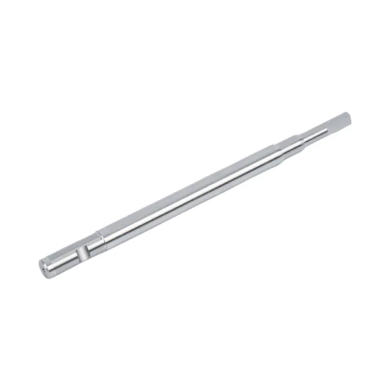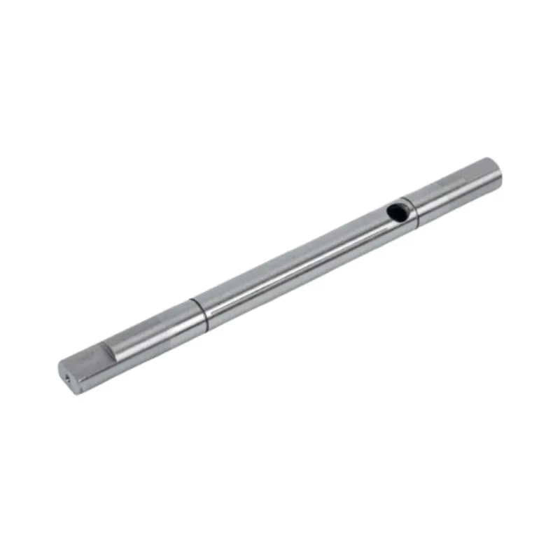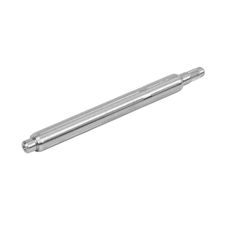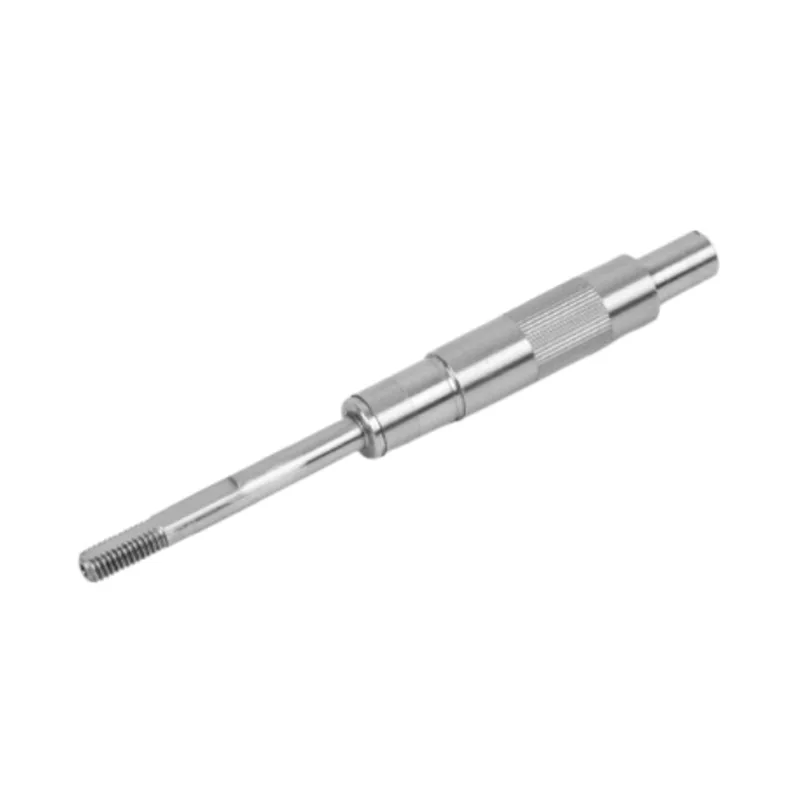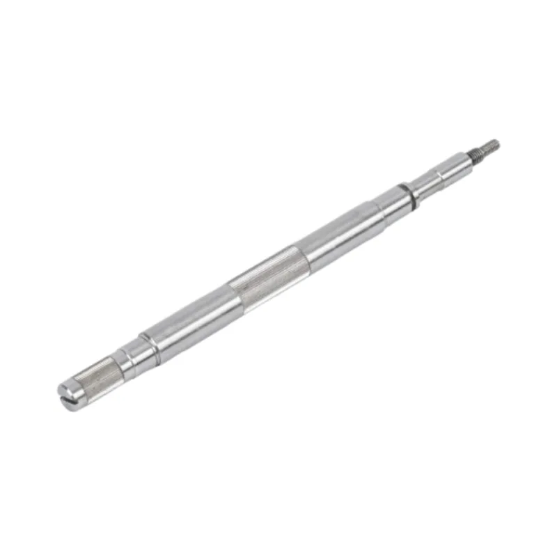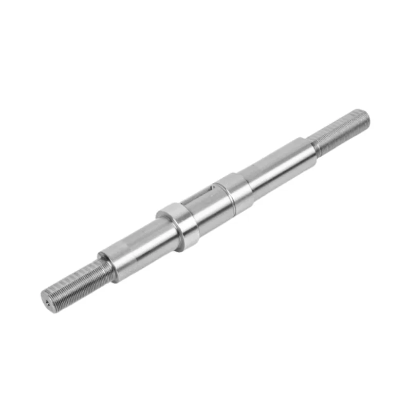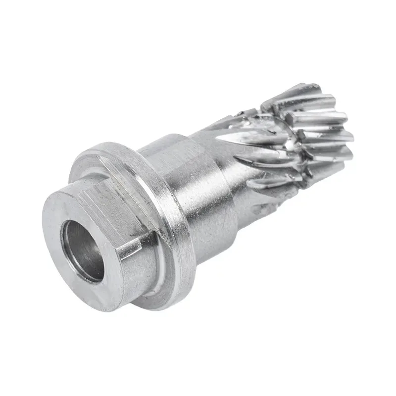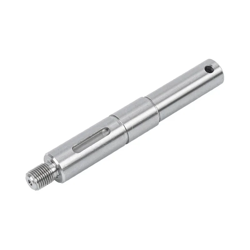

Before adding a second keyway, establish which hub it serves. Two slots on a shaft may carry two different connections, or they may work together inside one hub. Only the second arrangement raises the question of how two keys share one torque.
At the quotation stage, "double keyway for higher torque" leaves several decisions unresolved. Does the existing hub already have two slots? Is the problem peak load, repeated reversal or looseness after service? Will replacement hubs come from the same drawing and tolerance scheme?
We would settle those questions before pricing another milling operation. An extra slot is straightforward to describe on a shaft drawing. A second reliable load path requires agreement on the mating parts.
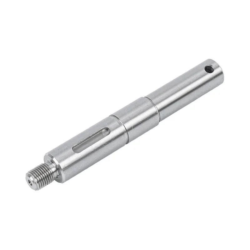
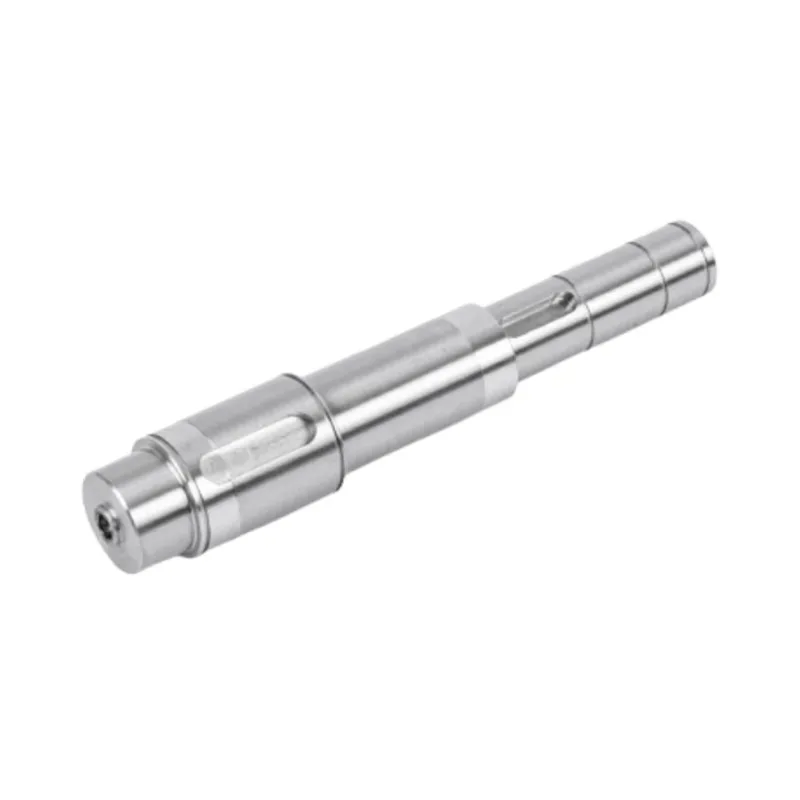
Two slots can describe very different assemblies
A key bridges a shaft keyway and a corresponding slot in the hub. For a conventional parallel-key connection, torque passes through contact at the working side faces. Count those connections, not just the visible grooves.
| Arrangement | Where torque passes | What to evaluate |
|---|---|---|
| One key in one hub | One keyed interface between that shaft section and hub | The key, shaft and hub under the specified duty |
| Two opposed keys in one hub | Two potential load paths across the same shaft-hub interface | Relative slot position, contact and unequal load sharing |
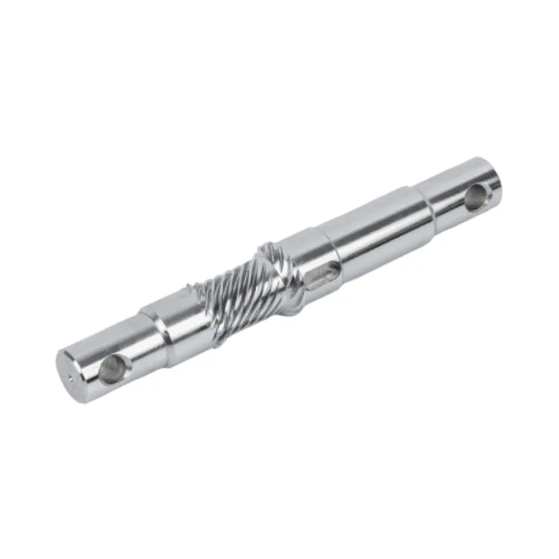
| Two axially separated slots serving separate hubs | A separate connection at each hub | The actual torque passing through each connection; capacities are not added simply because both slots are on one shaft |
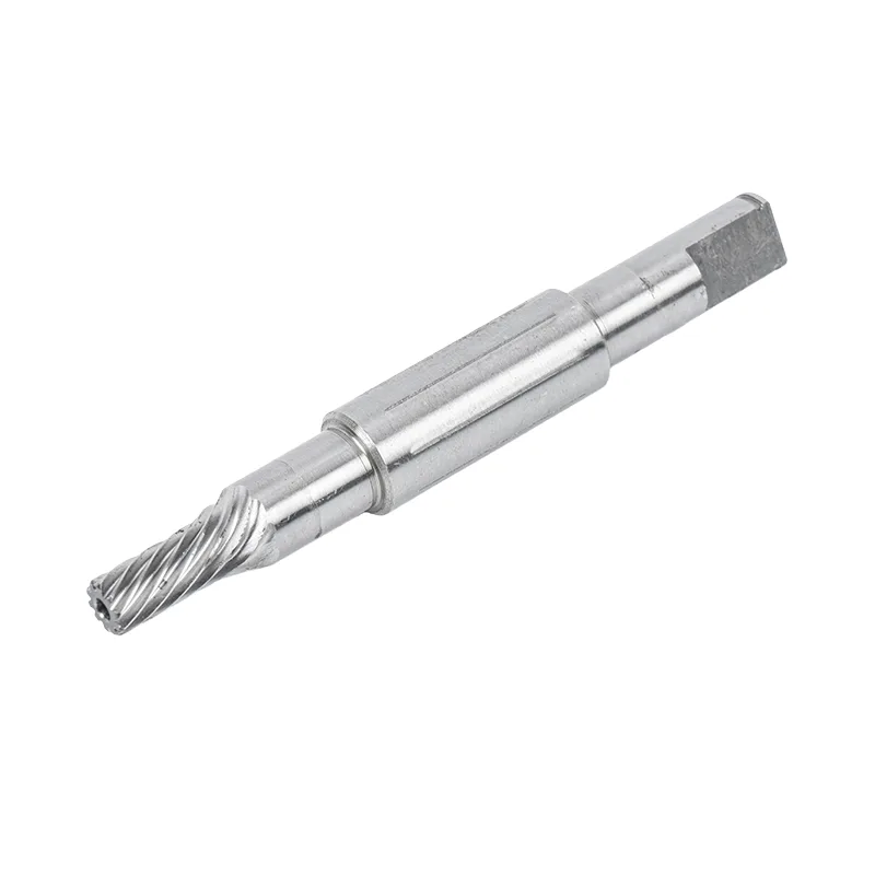
Guanshuo's double-keyed-slot design description specifies opposed keyways with a nominal angle of 180°. For an order using that arrangement, show both shaft and hub slots in the same cross-section. Also identify the axial engagement length. Two opposed grooves that do not engage the same hub cannot be assumed to share its load.
A second key creates another contact, not guaranteed equal contact
Imagine taking up clearance slowly in the driving direction. One key flank can touch before the other because the shaft slots, hub slots or keys differ slightly in position or size. That first contact begins carrying load while the other side is still taking up its clearance. Deformation and further rotation can change the share as torque rises.
This is why a calculation that simply assigns half the torque to each key needs justification. Parallel-key design methods account for unequal loading; the geometry is only one part of the model. Peak loads and changes in torque direction also matter.
There is a practical benefit to getting the second contact right: it provides another working interface for transmitting torque. But we would not approve a smaller shaft or a thinner hub solely because the drawing now contains two keys. Added keyways change the shaft section, and the hub material and wall geometry remain part of the strength review.
Read the published tolerances as separate requirements
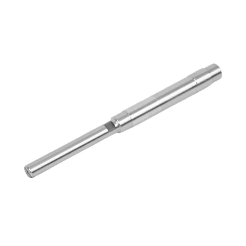
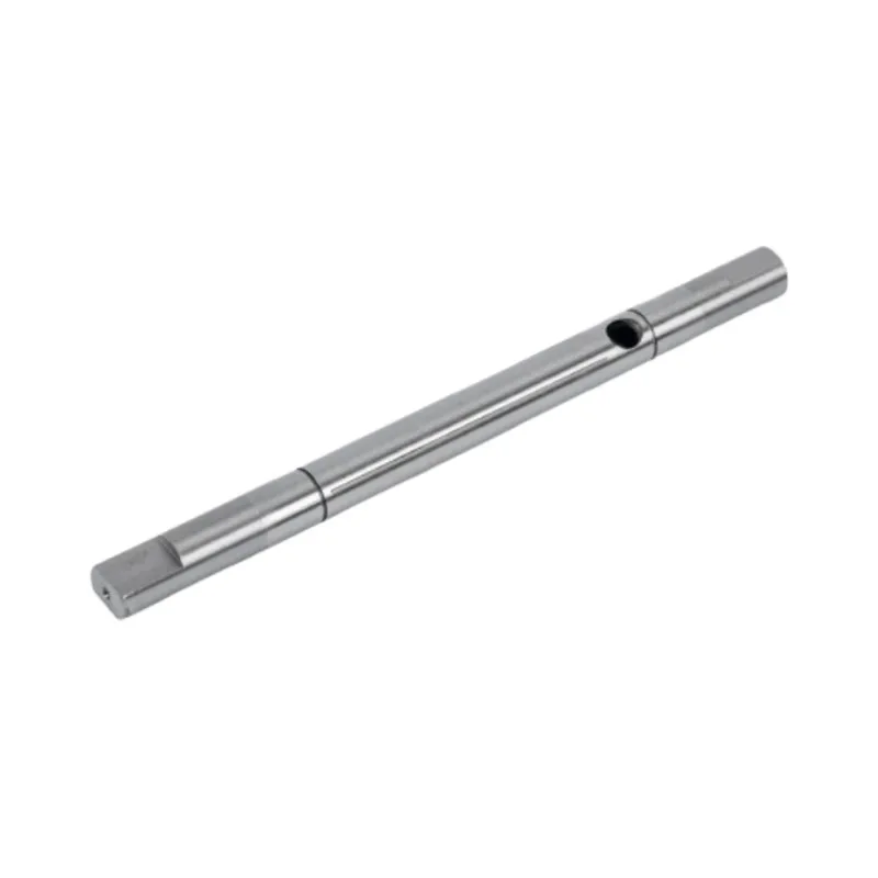
The single-keyway product lists keyway depth tolerance of ±0.1 mm and shaft-body roughness of Ra ≤0.8 μm. The double-keyed-slot page specifies 180°±0.5° between the keyways and parallelism error ≤0.02 mm in its structural description. Each number answers a different manufacturing question.
| Published requirement | What it describes | What it cannot establish alone |
|---|---|---|
| Double keyways: 180°±0.5° | Relative angular location around the shaft | The mating hub's slot angle or simultaneous flank contact |
| Double-keyway parallelism: ≤0.02 mm | A linear geometric control on the slot relationship | A substitute for the angular requirement or an assembled backlash limit |
| Single-keyway depth: ±0.1 mm | Variation in the specified groove depth | Key projection without the key height and mating hub depth |
| Single-keyway shaft body: Ra ≤0.8 μm | Finish of the shaft body | The finish, width or fit of the working keyway flanks |
Values apply to the named products. Define the exact features, datums, controlled lengths and acceptance limits on the order drawing. Tables scroll horizontally on small screens.
Guanshuo machines these products from carbon or alloy steel with quenching and tempering, and supports customized key width, depth and shaft geometry. Use that flexibility to specify the interface you need. A general product table is a starting point for the drawing, not a completed tolerance scheme for your hub.
What does half a degree mean at the shaft surface?
Angular tolerances can look small because they are written in degrees. Converting them into a displacement at a stated radius makes the assembly question easier to discuss.
A geometric check using the published angular tolerance
Take an illustrative shaft diameter of 20 mm, so the reference radius is 10 mm. At that radius, the arc displacement corresponding to 0.5° is:
s = r × Δθ, with Δθ in radians
s = 10 × (0.5 × π / 180)
s ≈ 0.0873 mm
This is the arc displacement of an angular reference at the shaft surface. It is not measured flank clearance, keyway width error or a prediction of backlash.
Now assume the hub also has a separately permitted 180°±0.5° slot-pair angle. If the shaft pair is at 180.5° and the hub pair is at 179.5°, their relative indexing difference is 1°. With one slot aligned, that corresponds to about 0.1745 mm of arc displacement at the same 10 mm reference radius.
The hub tolerance and 20 mm diameter are hypothetical. The exercise shows why two individually acceptable parts may still need a tighter coordinated interface definition. Actual assembly depends on key dimensions, the corner geometry, available clearance and deformation; these arc values must not be subtracted directly from a keyway width tolerance.
When a customer needs interchangeable hubs from more than one source, we would put the shaft and hub slot-pair tolerances next to each other during review. Accepting each drawing independently does not prove the pair is compatible. The ≤0.02 mm parallelism requirement also cannot be compared directly with an angular arc displacement: they control different errors.
The working flanks, key projection and usable length all matter
For a conventional clearance-top parallel-key arrangement, the intended torque contact is at the sides. The key must project sufficiently into the hub slot while retaining the specified top clearance. A hub that slides on does not prove either condition.
If the shaft keyway is deeper, a key of unchanged height sits lower. If it is shallower, the key projects farther. That is why the published ±0.1 mm groove-depth tolerance should be reviewed with the actual key height and hub-slot depth, rather than copied into an order on its own.
Keep the width requirements separate from depth. The working flank fit comes from the shaft slot, key and hub slot together. Specify which component retains the key and which interface needs assembly clearance. A blanket instruction to make everything a tight fit can create a part that is difficult to assemble without establishing the intended load sharing.
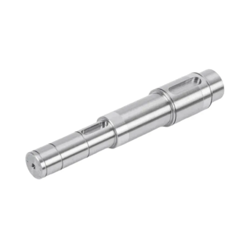
Mark the axial position of the hub on the shaft drawing or assembly section. Rounded ends, chamfers and partial overlap can reduce the length available for working contact. A longer groove outside the hub does not provide extra contact area inside it.
Review the reverse direction as a separate contact condition
A connection that takes up clearance smoothly in one direction may contact different flanks after reversal. Record both peak forward and peak reverse torque, how frequently direction changes, and whether braking or abrupt stopping creates a separate load case.
For a reversing drive with visible fretting or looseness, adding another keyway should follow diagnosis. Inspect the actual fit and contact regions, along with the shaft and hub material condition. If the problem is repeated movement within the connection, an extra groove alone does not define the missing clearance control.
Choose the simpler connection that meets the complete duty
| Situation | Factory review preference | Reason |
|---|---|---|
| A proven single-key assembly meets the new duty | Retain it unless another requirement has changed | Another key adds mating features and inspection obligations without an identified need |
| The connection needs more capacity within a restricted package | Evaluate opposed double keys with the hub included in the calculation | Two working interfaces may help, but their load split and the remaining sections need review |
| Two different hubs occupy separate axial positions | Design and rate each connection for its own torque path | Counting both slots does not establish a shared connection rating |
| Frequent reversals require very limited relative movement | Compare the keyed design with other connection arrangements | Flank clearance and reversal behavior may govern more than key count |
| Replacement hubs must be interchangeable | Agree on coordinated mating tolerances and representative assembly checks | A single hand-selected shaft-hub pair cannot establish interchangeability |
The motor shaft selection guide covers the broader choice of drive features. For this decision, keep the comparison at assembly level: the shaft, key or keys, hub, retention and required service access.
Approve the geometry and the assembled behavior separately
Guanshuo's double-keyed-slot process uses integrated CNC turning and milling with control of slot width, depth and position. The factory lists two-dimensional projectors and other precision inspection equipment. The inspection plan still needs to say which datum and method apply to each requirement.
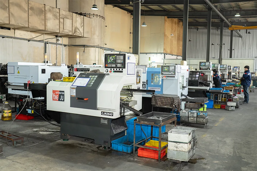
A dimensional report can show that the parts meet their drawings. Functional checks answer whether the chosen drawings deliver the required assembled behavior. Neither record should stand in for the other.
- Identify whether both keys engage one hub, and mark the actual overlap length.
- Record slot widths, depths and relative positions for shaft and hub, with key dimensions and material condition.
- Agree on the check for seating and contact. A contact-marking check may help locate engagement, but it does not quantify the torque split by itself.
- Define any forward and reverse functional test, including applied load, allowable relative movement and how movement will be measured.
- For interchangeable supply, choose an assembly-check plan that represents permissible mating variation rather than only one favorable pair.
- Separate first-article approval from the production-lot inspection plan.
Use our motor shaft inspection report guide to specify the records. For a quotation, send the hub section with the shaft drawing. That lets us address the connection you need instead of quoting two isolated grooves.
Frequently asked questions
Do double keyways double torque capacity?
No automatic doubling follows from adding a second keyway. The keys may carry unequal loads, and the shaft and hub still need strength checks. Rate the complete connection for its geometry, materials, fit and operating duty.
Are two slots at different shaft positions a double-key connection?
Not necessarily. If the slots serve separate hubs, each belongs to a different connection. Two-key load sharing applies when both keys engage the same hub and transmit torque across the same interface.
What angle does Guanshuo specify between opposed keyways?
Guanshuo's double-keyed-slot product specifies 180°±0.5°. The mating hub needs a coordinated angular requirement; the shaft value alone does not prove simultaneous contact or define assembled backlash.
Does keyway depth determine the key fit?
Depth affects key projection and available engagement, but it does not define the whole fit. Review shaft-slot width and depth, key dimensions, hub-slot geometry, top clearance and the working flank requirements together.
What should be supplied for a double-keyway shaft quotation?
Send the shaft drawing and mating-hub section, key dimensions, material and heat-treatment requirements, torque duty in both directions, assembly limits and inspection requirements. Identify whether interchangeability with replacement hubs is required.