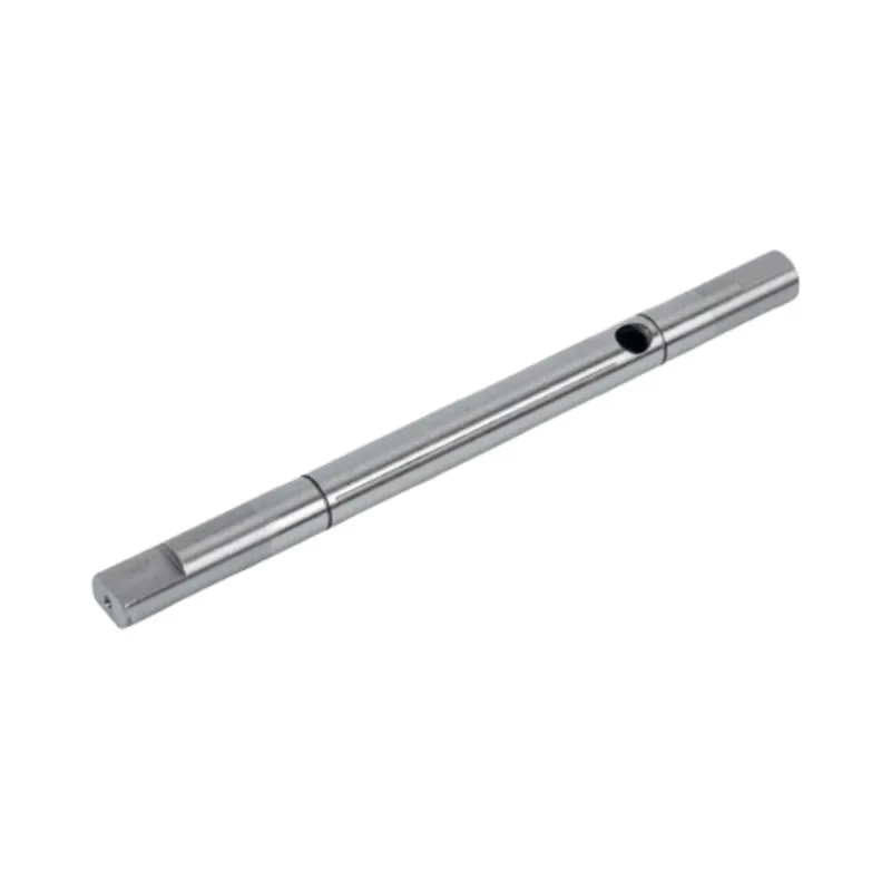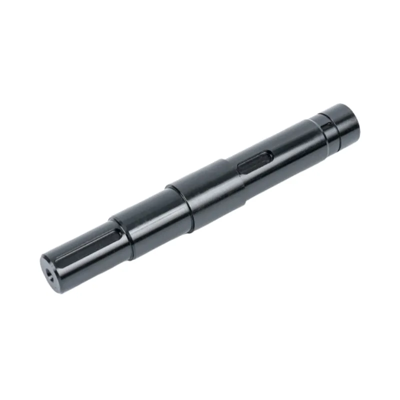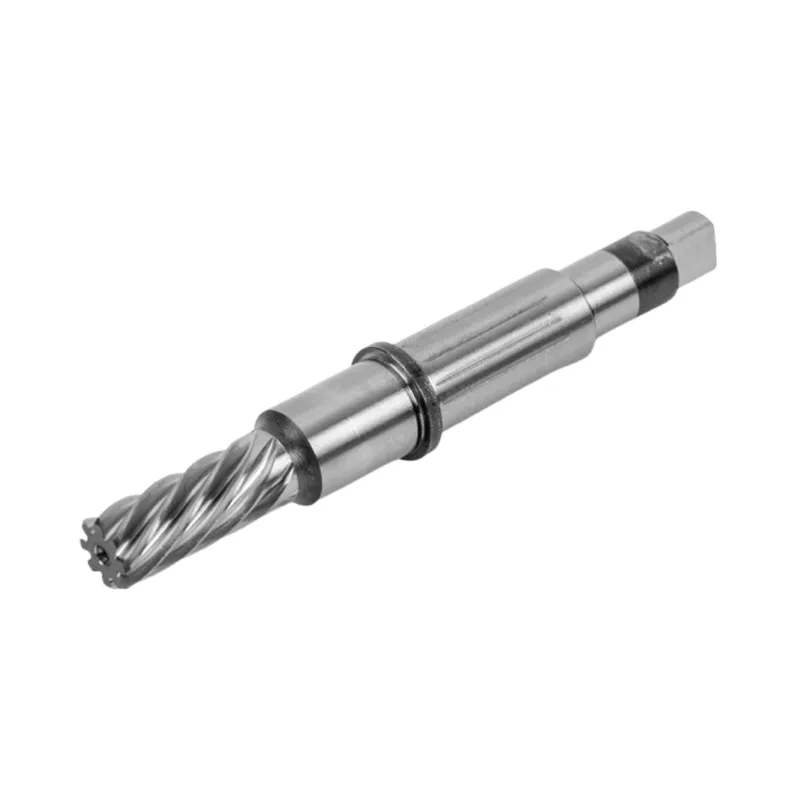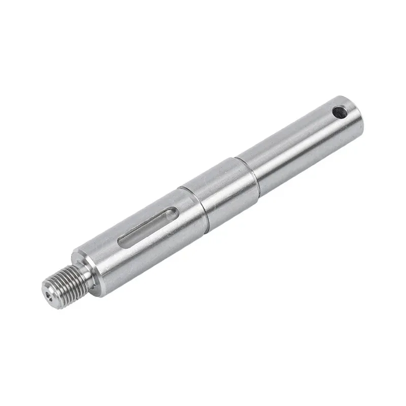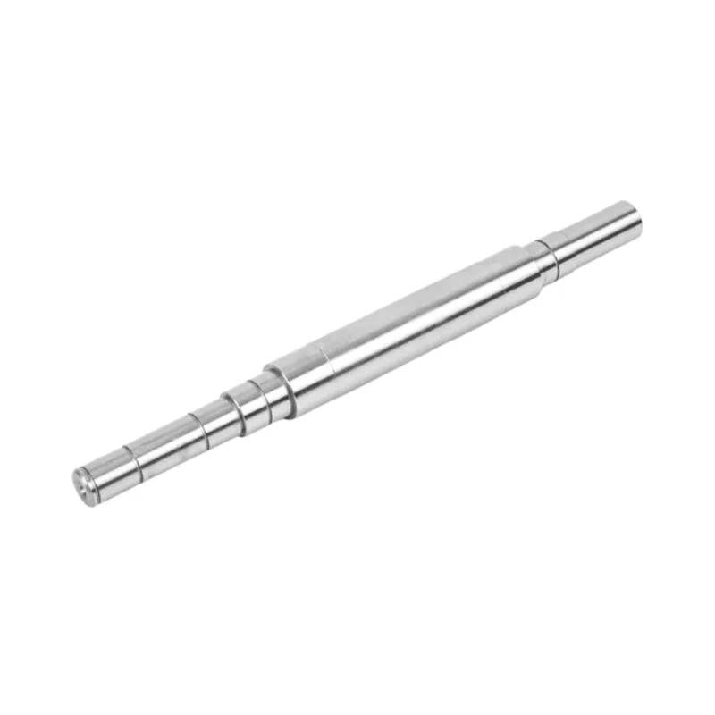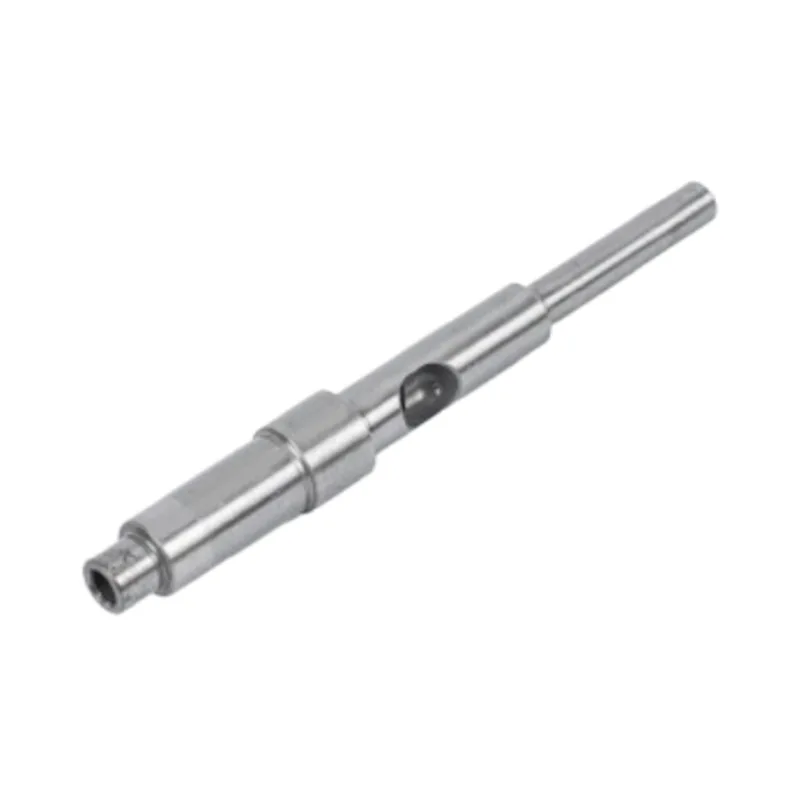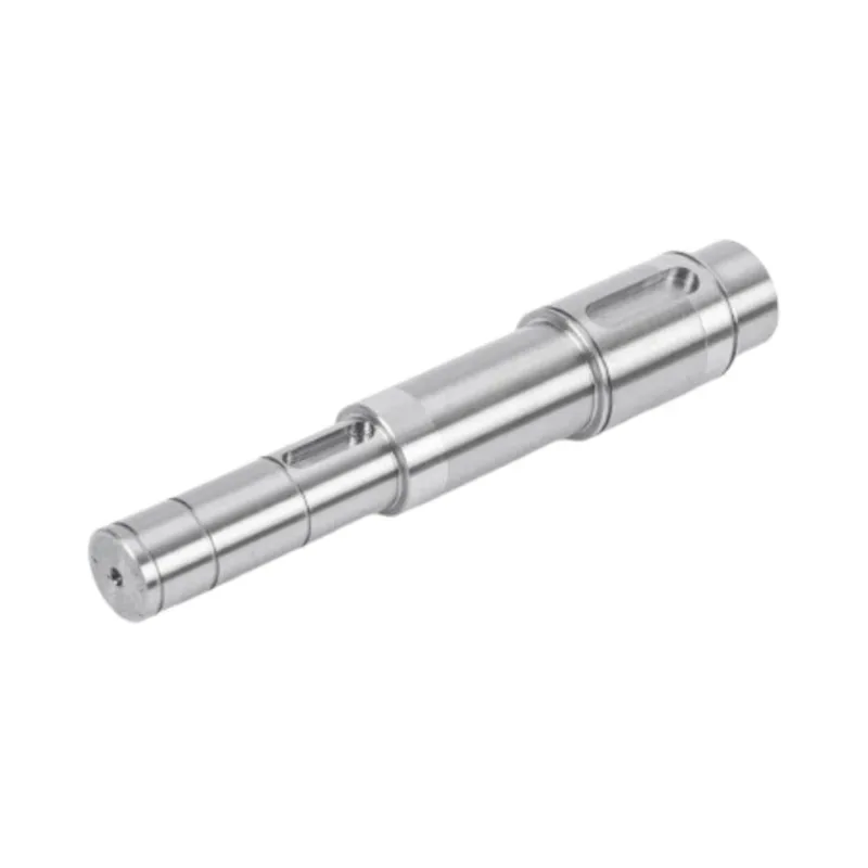

A shaft can rotate with very little indicated runout and still belong to a rotor that vibrates. The reverse can also happen: a rotor can meet its balance tolerance while a journal or seal land runs outside its geometric limit. These results are not contradictory. An indicator follows a surface. A balancing machine responds to mass distribution.
This distinction matters most when an RFQ says only dynamic balance G1 or low vibration. Both sound demanding. Neither is a complete acceptance requirement until the drawing names the speed, rotor mass and assembly state, correction planes, residual-unbalance limit and verification record.
Geometry, balance and machine vibration are three different acceptance layers
When a high-speed assembly is noisy, the shaft is an obvious suspect. That does not make every vibration problem a shaft-balance problem. The result can be influenced by the journal geometry, the rotor's mass distribution, fits and keys, bearing condition, coupling alignment, structural resonance, electromagnetic forces or the way the machine is mounted.
In our drawing reviews, we separate those layers before deciding what to tighten. Grinding a journal more accurately will not remove a heavy spot in an impeller. Removing mass from a rotor will not straighten a bent shaft. Lowering a residual-unbalance value may not cure a support resonance. Each action needs its own measurement.
| Check | What it controls | Typical output | What it does not prove |
|---|---|---|---|
| Diameter and fit | Size of bearing, rotor, seal or coupling seats | mm, tolerance class or fit | Straightness, runout or mass balance |
| Straightness and runout | Surface or axis geometry relative to the specified datum and setup | mm or μm | Where the rotor's center of mass lies |
| Dynamic balance | Residual mass unbalance in one or more correction planes | g·mm, mg·mm, or a stated grade at a stated speed | That journals meet their geometric tolerances |
| Complete-machine vibration | Response of the installed machine under defined operating conditions | Displacement, velocity or acceleration with speed and measurement location | That imbalance is the only excitation source |
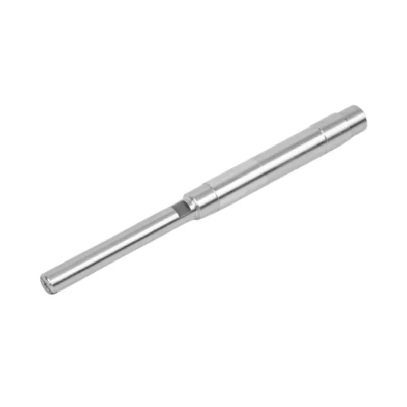
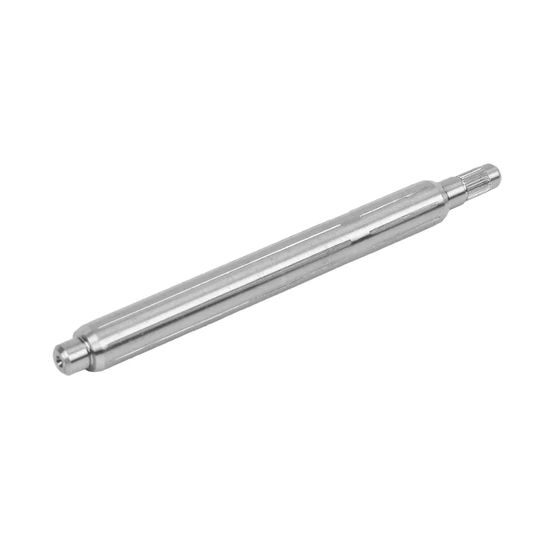
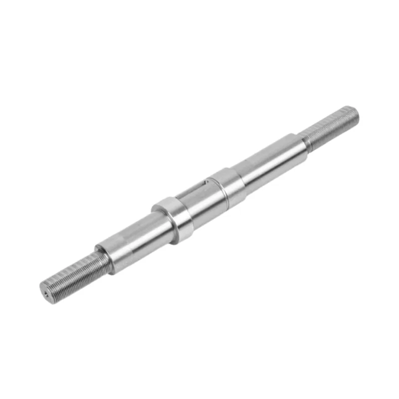
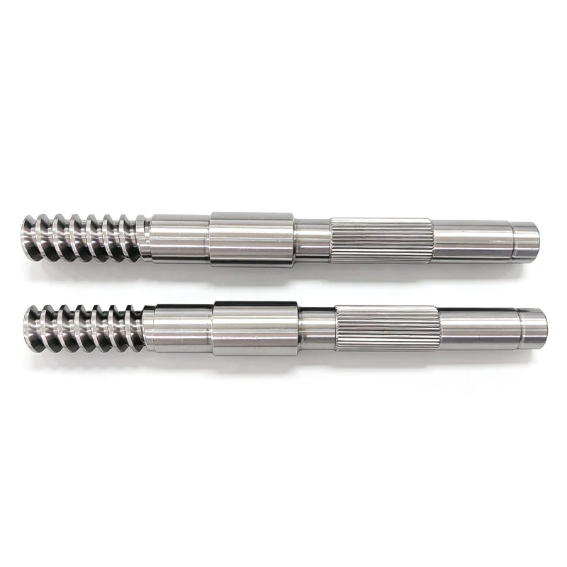
Guanshuo's current high-speed motor shaft page lists G1-level dynamic balance and shaft runout of 0.001 to 0.003 mm as separate product targets. That separation is correct and useful. For a custom order, each target still needs its own datum, test condition and acceptance record.
A G grade is a relationship, not a mass value
The letter and number are often treated like a simple quality rank: G1 sounds better than G2.5, so buyers ask for the smaller number. The missing detail is speed. Under the balance-quality relationship used for rigid rotors, G is the product of permissible specific residual unbalance and angular velocity. Its unit is mm/s.
Specific residual unbalance describes the allowed unbalance relative to rotor mass. For a simple static-unbalance picture, it can be visualized as a small offset between the mass center and rotation axis. As speed rises, the permissible offset for the same grade becomes smaller.
eper [μm] = 9,549 × G [mm/s] ÷ n [rpm]
Uper [g·mm] = eper [μm] × m [kg]
That is why G1 by itself cannot tell the balancing team the allowable g·mm. They need at least the rotor mass and service or maximum speed. They also need to know whether the rotor behaves rigidly across the relevant speed range and how the total tolerance will be allocated to the correction planes.
| Required field | Why it changes the result | Weak wording | Better direction |
|---|---|---|---|
| Governing standard and edition | Defines the terms, calculation and allocation method | Balance to ISO | State the applicable part, edition and any amendment or customer supplement |
| Reference speed | The allowable specific unbalance falls as rpm rises | For high speed | Give the service or maximum speed used for the calculation |
| Rotor mass | Converts specific unbalance into total permissible residual unbalance | Use drawing weight | Use the measured or controlled balance-state mass |
| Rotor state | Keys, retainers, magnets, fans and other parts change mass distribution | Balance shaft | List every installed and excluded component |
| Planes and allocation | A total value must be distributed correctly for a two-plane rotor | Dynamic balance | Name plane locations and the limit for each plane |
The grade becomes inspectable only after the calculation
Consider a hypothetical rigid rotor with a mass of 1.2 kg, a specified grade of G2.5 and a reference speed of 3,000 rpm. This is a teaching example, not a recommendation for a particular motor.
Uper = 7.96 × 1.2 = 9.55 g·mm
The result is a total permissible residual unbalance of about 9.55 g·mm before any required allocation to tolerance planes. If a simplified one-plane correction were made at a 20 mm radius, the equivalent correction mass would be:
This last number is an illustration, not an instruction to remove or add 0.48 g anywhere convenient. The permitted correction zones, available radii, rotor strength, direction and measured phase determine the real correction. A two-plane rotor also needs its total tolerance allocated to the planes rather than divided casually.
| Grade | Reference speed | Specific limit eper | Total Uper | Equivalent mass at 20 mm |
|---|---|---|---|---|
| G2.5 | 3,000 rpm | 7.96 μm | 9.55 g·mm | 0.48 g |
| G1 | 3,000 rpm | 3.18 μm | 3.82 g·mm | 0.19 g |
| G2.5 | 12,000 rpm | 1.99 μm | 2.39 g·mm | 0.12 g |
The table exposes two common mistakes. First, the same grade does not mean the same residual-unbalance value at every speed. Second, the correction mass depends on radius: a larger approved radius needs less mass for the same g·mm correction. That is why a report should show residual unbalance rather than stopping at grams added or removed.
Balance the state that will actually rotate
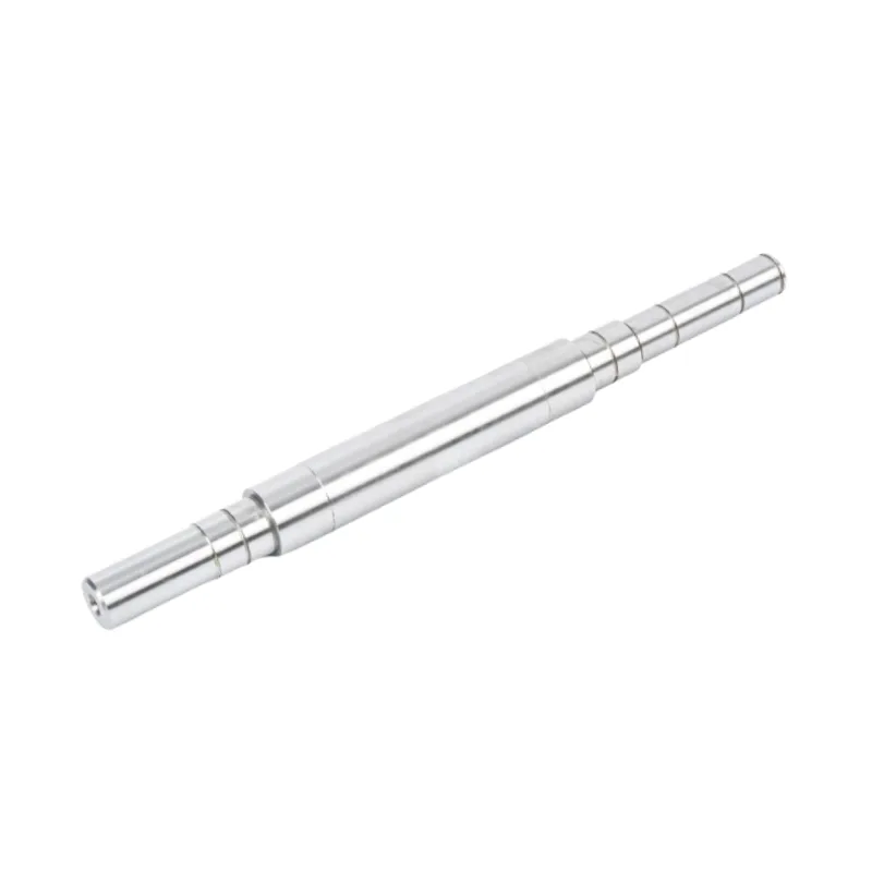
A bare motor shaft may be symmetrical enough that balancing it alone adds little value. Once the rotor core, magnets, fan, encoder target, coupling, pulley, impeller, fasteners, key and retainers are installed, the mass center can move. Fit clearance and seating faces can shift the mounted part away from the shaft axis even when each component passed inspection separately.
Our preference is to define the balance state from the final function and work backward. If the same shaft supports several customer-specific rotors, the shaft drawing should control its geometry and the rotor drawing should own the balance acceptance. If a subassembly will never be separated after balancing, test it in that stable state. If a service part is replaceable, define the interface and the replacement-balance strategy rather than assuming the original result survives every reassembly.
| Possible test state | Useful when | Main limitation |
|---|---|---|
| Bare shaft | The shaft has meaningful asymmetric features or is sold as a finished rotating component with a defined balance requirement | Does not include mass error introduced by the final rotor, key, fit or fasteners |
| Shaft plus rotor core | The core is permanently located and later components have separate controls | Any excluded fan, coupling or hardware can change the final result |
| Complete rotating assembly | The assembly state can be preserved through installation | Requires clear handling marks, orientation control and protection from reassembly changes |
| Installed machine or field balance | Service bearings, temperature, support and complete assembly materially affect response | It evaluates the installed system and may not isolate component-level causes |
Keys deserve an explicit line in the specification. Balancing the shaft and hub without a key, then inserting a full key during assembly, changes the mass state. The drawing or balance procedure should state the key convention and whether the key or simulated key remains in place.
One-plane and two-plane balancing correct different error patterns
A disk-like rigid rotor may be dominated by static unbalance, where one correction plane can bring the center of mass closer to the rotation axis. An axially extended rotor can also have couple unbalance: equal heavy effects at separated planes act in different angular directions. Its center of mass may sit near the axis while the principal inertia axis remains tilted. That condition needs two-plane information.
We avoid rigid rules such as choosing two planes from one length-to-diameter ratio. Bearing locations, correction-plane spacing, mass distribution, operating speed and the rotor's dynamic behavior all matter. ISO 21940-11 addresses procedures and tolerances for rotors with rigid behavior, including the number of correction planes and allocation of permissible residual unbalance. Rotors with flexible behavior require the different considerations covered by ISO 21940-12.
A flexible rotor can bend significantly as speed changes and can respond through more than one mode. In that case, a low-speed rigid-rotor result may not predict behavior through the operating range. The balance plan may need multiple speeds, additional planes or service-condition evaluation. The design owner should identify the rotor model and critical-speed context instead of using a stricter G number as a substitute for rotor-dynamic analysis.
The sequence determines whether the balance result survives production
Balancing should not be used to hide unstable geometry. If a bearing journal is out of round, a rotor seat has excessive runout or the part does not reseat consistently on the balancing fixture, the measured heavy spot can move between runs. We first want the rotation reference to be trustworthy.
The correction method belongs on the drawing or approved process. Drilling, milling, grinding, adding a qualified weight or changing a component may all alter strength, fatigue life, surface protection or airflow. A balancing operator should not choose a convenient surface that the designer intended to remain untouched.
The same applies to later operations. Pressing a component onto the shaft, welding, coating, heat exposure or disassembly after balancing can change the result. If a process occurs after the balance operation, the control plan should explain why it will not disturb the accepted state or should schedule a final verification after that process.
A useful balance report shows the inputs behind PASS
A certificate that says only G1 PASS is hard to audit. It does not reveal the speed used to calculate the limit, the mass entered into the machine, the assembly state or the values left in each plane. It also makes supplier-to-supplier comparisons unreliable.
| Report field | Question it answers |
|---|---|
| Part or rotor ID and drawing revision | Was the correct configuration tested? |
| Serial, lot or traceability ID | Can the result be tied to the delivered unit or batch? |
| Measured rotor mass and balance state | Which parts, key and hardware were present? |
| Standard, edition, grade and reference speed | How was the tolerance defined? |
| Correction-plane locations and radii | Where was unbalance measured and corrected? |
| Permissible residual unbalance per plane | What numerical limit applied to each result? |
| Initial and final residual unbalance with phase | What changed, and what remained after correction? |
| Correction method and locations | Was the approved process used? |
| Machine, tooling and operator or program ID | Can the setup and result be traced? |
| Date and acceptance decision | When was the final state verified? |
The balance report should be linked to, but not confused with, the shaft inspection report. Guanshuo's motor shaft quality inspection guide explains the wider dimensional and material record. For tight rotating geometry, the precision grinding page shows the shaft-level process context. Balance acceptance is an additional record for the specified rotor state.
Vibration at running speed is a clue, not automatic proof of imbalance
Mass unbalance commonly produces a once-per-revolution response, often written as 1× rotational speed. That makes 1× vibration a useful lead. It is not a verdict. Misalignment, looseness, eccentric components, bent shafts, bearing-related effects, resonance and electrical excitation can alter the spectrum and phase pattern.
| Observation | Possible questions to investigate | Do not assume |
|---|---|---|
| Low shaft runout, high residual unbalance | Is the rotor core, fan, key or coupling mass asymmetric? Is the assembly state correct? | That better grinding alone will solve it |
| Balance result changes after reseating | Are journals round and clean? Is the fit loose? Does tooling center repeatably? | That the rotor itself changed mass |
| Rotor passes balancing, installed machine vibrates | Check assembly orientation, bearings, alignment, support stiffness, resonance and operating conditions | That the balance certificate guarantees total machine vibration |
| 1× vibration rises sharply near one speed | Could a structural or rotor resonance be amplifying a modest excitation? | That an extremely small G grade is the only remedy |
| Good balance before coating or repair, poor result after | Was mass added or removed unevenly? Did heat or handling alter geometry? | That the earlier report still represents the final state |
| Good shaft, inconsistent assembled rotor | Are the mating bore, locating face, key and fastening sequence controlled? | That every fault belongs to the shaft supplier |
For a bent or heat-treatment-distorted shaft, correct the geometry at the proper stage before asking balancing to compensate for it. The process logic is covered in our guide to shaft straightening after heat treatment. For runout terminology and datum selection, use the drawing's geometric-tolerancing system and keep the measurement setup consistent with the functional bearing or rotor seats.
Write the RFQ so two suppliers calculate the same limit
The block below is intentionally incomplete. Replace every bracketed field with the design decision for the actual rotor. If one field cannot be filled, that is the engineering conversation to have before production, not after a vibration complaint.
ROTOR / PART ID: [drawing number and revision]
BALANCE STATE: [all included and excluded components]
KEY CONVENTION: [full key / half key / no key / defined customer method]
GOVERNING STANDARD: [standard, part, edition and amendment]
ROTOR BEHAVIOR: [rigid / flexible / design owner to confirm]
BALANCE QUALITY GRADE: [G value]
REFERENCE SPEED: [rpm used for tolerance calculation]
MAXIMUM SERVICE SPEED: [rpm]
ROTOR MASS FOR CALCULATION: [kg, measured or controlled]
CORRECTION PLANES: [number, axial positions and radii]
PERMISSIBLE RESIDUAL UNBALANCE: [g·mm per plane]
ALLOWED CORRECTION: [method and permitted zones]
FINAL OPERATIONS AFTER BALANCE: [list or none]
VERIFICATION: [reseating requirement and acceptance rule]
REPORT: [required fields and traceability level]
SHAFT GEOMETRY: [datum, journal runout and inspection condition]
INSTALLED VIBRATION REQUIREMENT: [separate system-level criterion, if applicable]
The high-speed product page lists shaft diameters from 5 to 50 mm, h5/h6 outside-diameter tolerances, G1-level dynamic balance and shaft runout of 0.001 to 0.003 mm. Those are useful starting capabilities for the named product family, not a substitute for this RFQ block. The final drawing should state the exact limits that apply to the selected material, geometry, rotor and speed.
Frequently asked questions
Is dynamic balance the same as shaft runout?
No. Shaft runout measures geometric variation of a surface while it rotates about a defined datum axis and setup. Dynamic balancing evaluates residual mass unbalance in one or more correction planes. Low runout helps the rotor seat and measure repeatably, but it does not prove that the mass center and principal inertia axis are correctly aligned.
What does a G1 balance grade mean?
G1 is a balance quality grade with a value of 1 mm/s in the balance-quality relationship. It is not a residual-unbalance value by itself. The reference speed and rotor mass are needed to calculate the permissible residual unbalance, and a two-plane rotor needs the total tolerance allocated to its planes.
Should a motor shaft be balanced before or after rotor assembly?
Balance the state that represents the rotating product being accepted. A bare shaft can be checked when it has meaningful asymmetric features or a shaft-only requirement, but that result does not include mass error from the rotor core, magnets, fan, key, coupling or fasteners. If the complete assembly remains intact through installation, final-assembly balancing usually represents service mass more closely.
Is one-plane balancing enough for a motor rotor?
It depends on rotor geometry and dynamic behavior. A disk-like rigid rotor dominated by static unbalance may be suitable for one-plane correction. An axially extended rotor with couple or general dynamic unbalance needs two-plane information. Flexible rotors can require multiple speeds or additional planes. The balance procedure should make the decision, not the word motor alone.
What should a dynamic balance report include?
At minimum, include the rotor ID and revision, traceability ID, measured mass, balance state, key convention, governing standard and edition, grade, reference speed, correction-plane locations and radii, permissible residual unbalance per plane, initial and final results, correction method, equipment or program identification, date and acceptance decision.