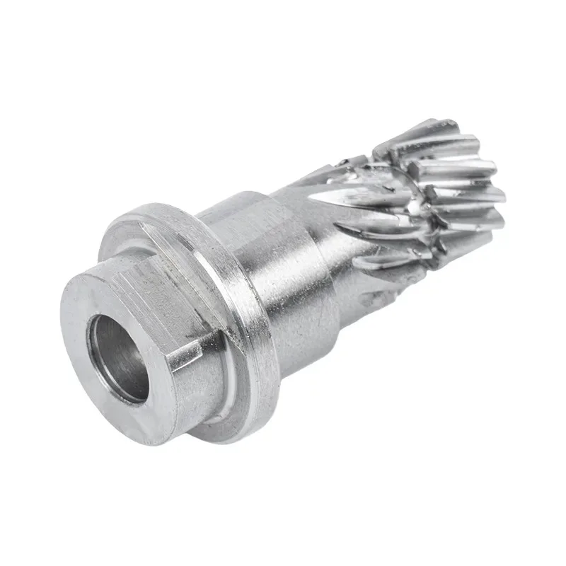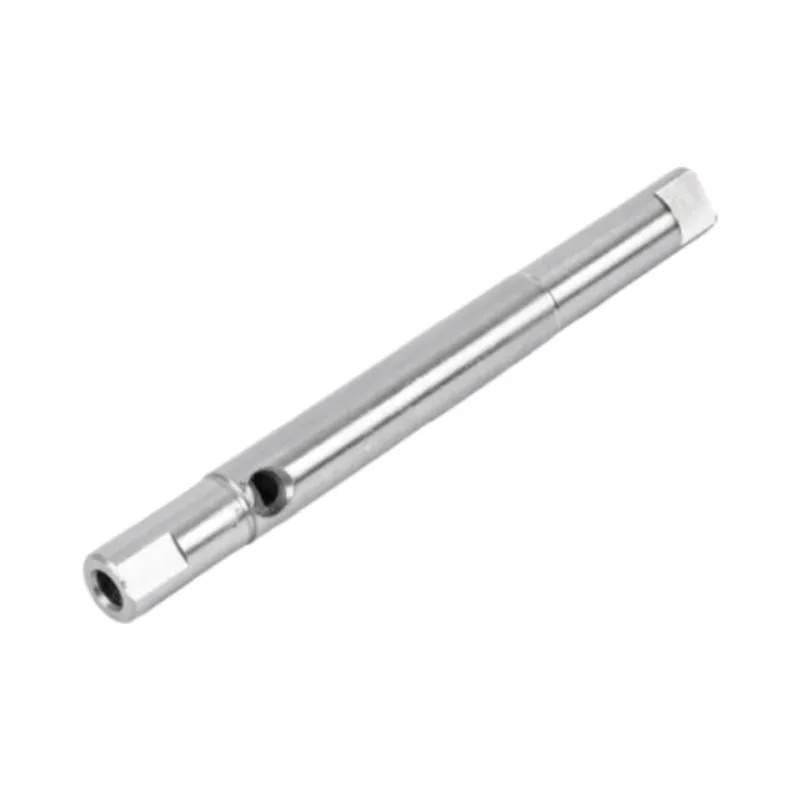

A shaft can pass every diameter check and still put a bearing, rotor or encoder in the wrong place. The cause is often a drawing that controls each feature alone but never calculates how the limits interact.
We review a shaft from the assembly backward. First, what must fit? Then, which surfaces establish the rotating axis and axial location? Only after that do we decide where a tight size tolerance, a geometric control or a direct datum dimension earns its cost.
IT6 and h6 do not say the same thing
The number in an ISO tolerance designation describes a grade, which determines the tolerance width for a given nominal-size range. The letter places that tolerance zone relative to the nominal size. A note such as IT6 gives a width class but does not, by itself, tell the manufacturer where the shaft limits sit. A designation such as h6 combines the shaft-zone position h with grade 6.
ISO 286-1 defines the code system and fit terminology. ISO 286-2 provides the standard limit deviations for hole and shaft classes. The current editions remain ISO 286-1:2010 and ISO 286-2:2010; Part 1 was reconfirmed in 2026. A buyer should still identify the standard and edition used by the drawing, especially when supplier and customer templates come from different systems.
Guanshuo's precision-ground smooth shafts reach IT5-IT6 dimensional accuracy, Ra at or below 0.4 μm and straightness at or below 0.01 mm for that named process. Its single-step motor shaft uses g6/h6 for the working diameter and step-face perpendicularity at or below 0.02 mm. These are separate controls on separate product scopes. They should not be collapsed into one generic claim that every shaft is "IT6."
| Control | What it limits | What it does not establish |
|---|---|---|
| Size limits or tolerance class | The permitted local size of a diameter or width | A complete, explicit requirement for roundness, straightness or alignment under every drawing system |
| Fit between two parts | The possible clearance or interference from both sets of limits | Axial shoulder position or rotating accuracy |
| Form control | The shape of one feature, such as straightness, roundness or cylindricity | Its position or orientation to a separate datum unless specified |
| Location, orientation or runout control | The relationship of a feature to a stated datum or datum system | The feature's size limits |
| Surface roughness | Fine texture on the specified surface | Diameter, roundness, runout or fit |
The governing drawing standard and modifiers determine how size limits interact with form. We still prefer explicit geometric controls when the function depends on them. We push back when a drawing solves every problem with a tighter diameter. If the complaint is axial position, the shoulder dimension needs attention. If it is rotating error, look at the datum axis and geometry. Making a bearing seat two micrometres tighter will not correct a misplaced shoulder.
The fit lives between four limit sizes
A nominal 20 mm shaft and a nominal 20 mm bore do not reveal whether the assembly will slide, press or switch between the two. Calculate the smallest and largest possible gap from the actual limits.
The minimum clearance pairs the smallest hole with the largest shaft. The maximum pairs the largest hole with the smallest shaft. Reversing either combination gives a comfortable-looking result that the production limits do not guarantee.
This calculation also exposes a common RFQ gap: the shaft drawing arrives without the mating bore limits. The factory can make the shaft exactly as drawn, but it cannot confirm the assembly fit from one component alone. Send the bearing, rotor or hub designation and the relevant housing or bore limits.
| Question | Why it changes the decision |
|---|---|
| Which component must move or remain fixed? | A sliding assembly and a torque-transmitting press fit do not use the same limit strategy. |
| Are the shaft and bore at the same temperature? | Different temperatures or materials change their sizes by different amounts. |
| Which surface carries the load? | A bearing inner ring, rotor lamination stack, seal and coupling impose different functional requirements. |
| Will plating, coating or final grinding change the diameter? | The drawing must state whether limits apply before or after the final surface operation. |
| How will assembly force and damage be controlled? | A fit that exists on paper can still be impractical if the assembly method is undefined. |
Shoulder dimensions add even when inspectors check them separately
Stepped shafts locate parts along the axis. If a bearing sits against one shoulder and a rotor stops against another, the distance between those faces matters to the assembly. A chain of individually acceptable dimensions may leave that distance outside its functional limit.
In the example, the nominal A-to-C distance is 57.00 mm. Its worst-case limits are 56.93 and 57.07 mm. If the assembly requires 57.00 ±0.04 mm, both L1 and L2 can pass while A-to-C fails.
A direct A-to-C dimension from the functional datum can protect that relationship, but do not add it as a second independent size that conflicts with the chain. Decide which dimensions control and which are reference information under the drawing system in use.
Statistical root-sum-square calculations can predict a narrower distribution than worst case, but they do not change individual part limits. Use a statistical stack only when the process distributions, centering assumptions and acceptance method are documented and accepted. For a basic drawing review, worst case is the honest starting point.
Shoulder geometry matters too. A sharp corner, fillet or undercut can prevent a bearing ring or spacer from reaching the nominal face. The stepped-shaft shoulder guide covers that contact problem in detail. Tolerance stack-up should use the surface that the mating part can physically reach.
Two correct diameters can still rotate on different axes
Micrometers answer size. They do not prove that two bearing journals share an axis or that a rotor seat runs true to that axis. This is why a complete shaft drawing uses geometric controls as well as size limits.
ISO 1101:2017 provides the current symbol language for form, orientation, location and runout. ISO 5459:2024 covers datums and datum systems. The exact callout must follow the customer's selected GPS or GD&T system, but the design logic is universal: the datum should represent how the shaft is located when it works or when the agreed inspection setup simulates that condition.
From a factory viewpoint, the hardest drawings are not always the ones with the smallest numbers. They are the ones that put a tight runout callout on a surface but leave the rotation axis undefined. We can measure a number, but buyer and supplier may create different numbers from different setups.
Guanshuo holds straightness at or below 0.01 mm on its precision-ground smooth shafts and step-face perpendicularity at or below 0.02 mm on its single-step product. Use those figures as product-specific capability references. A custom drawing still has to name the controlled feature, datum, span and final production condition.
A ten-degree temperature difference can become a micrometre problem
ISO 1:2022 sets 20 °C as the standard reference temperature for geometrical and dimensional properties. That does not mean every shop must remain at exactly 20 °C every second. It means a dimensional result needs a known reference and suitable correction or stabilization when temperature effects are significant.
NIST lists 11.5 × 10⁻⁶/°C as a representative coefficient for a short steel gauge block. Real shaft materials vary, so the following is an illustration rather than a correction value for every steel.
A steel shaft and steel ring at the same temperature may expand by similar proportions. A hot shaft entering a cooler bearing, or a steel shaft mating with another material, is different. Do not use the single-part calculation as an assembly-clearance prediction without the second component.
For tight work, the inspection report should record or control the relevant measurement condition. A diameter reported to the micrometre without a credible temperature state can look more certain than it is.
Allocate tolerances to the operation that can create them
Turning creates the overall form efficiently. Heat treatment may move the material. Straightening corrects the hardened blank where needed. Grinding then establishes the final running diameters and texture. Inspection confirms the relationships on the finished part.
This sequence is why we do not treat all tolerances as title-block decorations. A final bearing-seat size, the runout of a rotor seat and the position of a shoulder may depend on different setups. The routing has to preserve a common datum strategy between them.
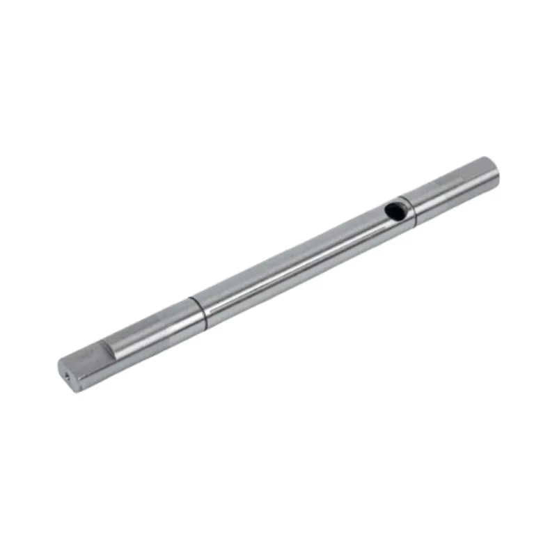
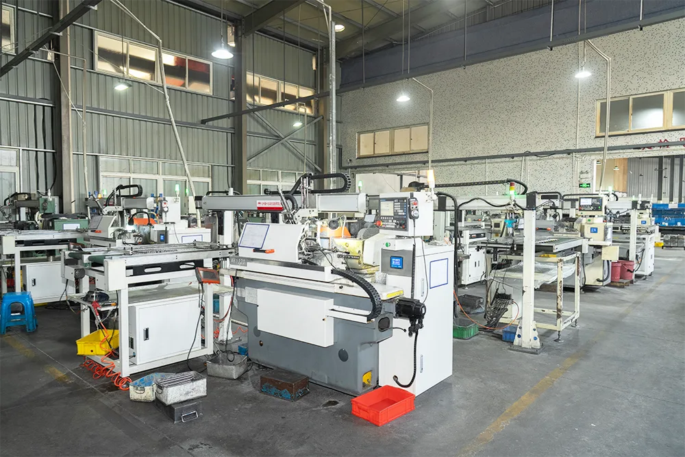
Cylindrical and centerless grinding solve different setup problems. The grinding-method comparison explains when each route suits a shaft. Surface texture is a separate decision; use the motor shaft roughness guide to assign Ra only to surfaces that need it.
A tighter tolerance also changes inspection time, scrap risk and process stability. That does not mean a buyer should relax a functional requirement. It means the drawing should spend precision where the assembly uses it and avoid putting the same limit on clearance diameters, unfinished reliefs and decorative surfaces.
Every tolerance needs a location, datum and measurement stage
The final inspection plan should follow the same stack used by the designer. If the assembly depends on A-to-C shoulder distance, recording L1 and L2 alone leaves the functional result to arithmetic. Include the calculated or directly measured characteristic that releases the assembly.
| Characteristic | Reference and stage | Useful evidence |
|---|---|---|
| Bearing journal size | Named journal, after heat treatment and final grinding | Actual limit-size measurements at agreed sections |
| Fit with mating bore | Calculated from approved shaft and bore limits at the stated reference condition | Minimum and maximum clearance or interference calculation |
| Shoulder stack | Functional datum face and all contributing axial dimensions | Individual values plus the resulting functional distance |
| Rotor-seat runout | Agreed bearing-journal datum axis, final condition | Actual runout and documented setup |
| Journal straightness or cylindricity | Controlled feature and axial span | Named characteristic and actual result, not a generic "straight" check |
| Surface roughness | Exact bearing or seal land after its final finish | Ra result with surface location and measurement direction where required |
| Temperature-sensitive size | Approved reference and measurement condition | Part temperature or stabilization/correction record when required |

The motor shaft inspection guide gives the wider report structure. For a tolerance-stack project, ask for actual values on the contributing dimensions. Pass/fail marks hide whether the stack is centered or whether several features are drifting toward the same assembly limit.
Before quotation, send the mating-part limits, the shaft drawing and the assembly condition. Mark the critical fit, the axial locator and the functional rotating axis. If temperature, coating thickness or a post-grind state affects acceptance, state it in the same package. This gives the factory enough information to propose a process and measurement route without inventing the missing design intent.
Frequently asked questions
What is a motor shaft tolerance stack-up?
It is the combined effect of all permitted dimensional variations along a functional path. For an axial stack, the worst-case tolerance is the sum of the contributing limits in that path. For a shaft-to-bore fit, the result comes from the four hole and shaft limit sizes.
Is IT6 the same as h6?
No. IT6 is a standard tolerance grade that defines a tolerance width for a nominal-size range. h6 is a shaft tolerance class that combines the h fundamental-deviation position with grade 6. A grade alone does not locate the tolerance zone relative to nominal size.
Can two journals pass diameter inspection and still have excessive runout?
Yes. Diameter inspection checks size. Runout checks how a surface varies as the shaft rotates about a stated datum axis. The journals can meet their size limits while their axes or another rotating surface are misaligned.
Should I use worst-case or statistical tolerance stack-up?
Use worst case when every permitted combination must assemble. A statistical method may predict a narrower production distribution, but it requires validated process data, centering assumptions and an agreed acceptance method. It does not change the drawing limits of an individual part.
What information should I send for a motor shaft tolerance review?
Send the shaft drawing and mating-part limits, identify the functional bearing or journal datums, show the axial locator and rotating axis, and state final process conditions such as heat treatment, grinding or coating. Include the reference temperature and inspection-report requirements when they affect acceptance.