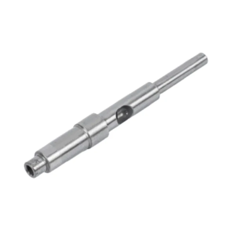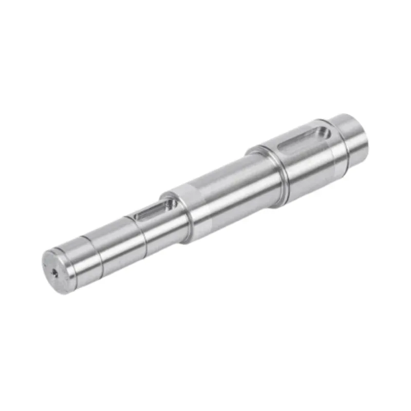

A note such as concentricity 0.01 looks precise until the shaft reaches the inspection room. One inspector may place the part between centers and read a dial indicator. Another may support two journals on rollers. A third may construct two axes from measured points. Those are different tests, and they do not have to return the same number.
From a factory viewpoint, the assembly should choose the term. A bearing journal, seal land, rotor seat and center hole can each define a different relationship. The drawing has to say which one controls the shaft.
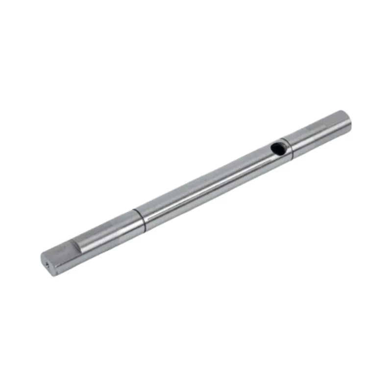
Five similar words answer five different questions
Runout, concentricity and straightness are often grouped under "shaft accuracy." That shorthand is fine in a meeting, but it is too loose for a drawing or inspection report. Each control sees a different part of the geometry.
| Control | Question it answers | Datum required? | What it does not prove by itself |
|---|---|---|---|
| Straightness | Does the controlled surface line or derived median line stay inside its straightness zone over the stated length? | No. It is a form control. | How the feature runs relative to a bearing journal or other datum axis. |
| Circularity | Is each measured circular cross-section round within its tolerance zone? | No. It is a form control. | Whether that circle is centered on another journal or rotation axis. |
| Circular runout | How much does the surface vary at one cross-section during rotation about the datum axis? | Yes. | Variation along the full length of the surface. |
| Total runout | How much does the entire controlled surface vary as the shaft rotates and the probe traverses its length? | Yes. | Mass imbalance or the behavior of a complete rotor assembly at speed. |
| Coaxiality or concentricity | How is a derived axis or set of derived centers located relative to a datum axis under the governing drawing system? | Yes. | A simple surface TIR value unless the specification and verification method make that relationship explicit. |
A diameter measurement is missing from the table because size is another question again. A micrometer can confirm that a journal is inside its size limits. It does not establish roundness, straightness or how that journal rotates relative to another feature.
If the drawing says "concentricity," identify the drawing language first
The same word can trigger different expectations under different company practices and standards. ISO 1101:2017 remains the current ISO foundation for geometrical tolerancing of form, orientation, location and runout. ASME Y14.5-2018 is the current American dimensioning and tolerancing standard, and ASME training for that edition treats concentricity and symmetry as legacy controls. Position, circular runout or total runout may express the intended function more directly under the ASME system.
That does not mean an old drawing is automatically wrong. It means the title block matters. A supplier should not silently reinterpret an ASME Y14.5-2009 concentricity symbol as a 2018 position or runout control, and it should not translate an ISO callout into ASME language by habit.
| Functional concern | Control to evaluate | Why |
|---|---|---|
| A seal or bearing surface must rotate true to the bearing-journal axis | Circular or total runout to the functional datum axis | The assembly cares about the actual surface during rotation. |
| A bore or cylindrical feature axis must stay inside a location zone | Position or coaxiality under the selected standard | The requirement concerns a derived axis, not one indicator trace on the surface. |
| A long shaft blank must not bend beyond a form limit | Straightness over a stated length and production stage | The part needs a form control before or after the process that can move it. |
| One journal must be round by itself | Circularity or cylindricity | A datum relationship is unnecessary when the problem is local form. |
| A rotor vibrates at operating speed | Geometric inspection plus a separate balance and assembly investigation | Low runout does not prove that mass is evenly distributed around the rotation axis. |
The practical distinction is surface behavior versus derived geometry. Runout is often the more direct language for a seal land, bearing seat or rotor seat because those are working surfaces. A CMM-derived axis may be appropriate for a bore or feature-location problem. Neither method is universally better; each answers a different engineering question.
A TIR number contains more than eccentricity
A dial indicator reading is usually reported as total indicated runout, or TIR: the difference between the highest and lowest readings during the specified rotation. It is a useful shop-floor result, but it is not a pure measurement of axis offset.
The indicator sees everything that moves its probe. That can include eccentricity of the measured surface, out-of-roundness, waviness, dirt or a burr, error in the datum surfaces, and error in the fixture or spindle used to rotate the part. The measured value belongs to the complete setup.
This leads to one of the most expensive shortcuts in shaft inspection: dividing every TIR result by two and calling the answer eccentricity. That relationship holds only for an ideal round surface rotating around a fixed axis with negligible fixture and spindle error. When form and setup error contribute to the trace, the division invents certainty that the measurement does not contain.
Record the TIR as measured. If the design needs eccentricity or a derived-axis relationship, use a method that can separate the required geometry and evaluate it under the drawing standard.
The support method can change the result
A runout value without a setup is incomplete. The same shaft may be measured between its center holes, on its bearing journals, in a collet or on a measuring spindle. Each setup creates a different rotation axis and adds its own error sources.
| Setup | Axis being simulated | Useful for | Main limitation to control |
|---|---|---|---|
| Between centers | The axis created by the center holes | Parts ground between centers and checks tied to that manufacturing reference | Damaged, dirty or nonfunctional center holes can dominate the result. |
| Two journals on rollers or suitable supports | The axis created by the supported outside diameters | Approximating how bearing journals locate the shaft | Journal roundness, lobing, support spacing and contact geometry affect the reading. |
| Chuck or collet | The machine or fixture spindle axis transferred through the clamped feature | Process checks and features made in the same setup | Chuck runout, clamping force, jaw condition and reseating error enter the result. |
| Roundness or cylindricity instrument | A constructed measurement axis under the instrument's setup and evaluation rules | Separating form and axis relationships across sections | Centering, leveling, filter settings, sampling and evaluation method must be controlled. |
| CMM or scanning measurement | A datum reference frame built from measured features | Derived axes, position and complex feature relationships | Point density, probe strategy, feature construction and software evaluation affect the result. |
Between centers is not automatically more accurate than journal support. It is more relevant when the center holes represent the process or inspection datum. If the shaft runs in two bearing journals and the center holes have no assembly function, the drawing may need the bearing surfaces to establish the datum instead.
This is also why a dynamic balancing result cannot replace geometric inspection. A balancing machine addresses mass distribution in a rotor or assembly. A dial indicator addresses surface movement in its fixture. One part can pass either test and fail the other.
The functional datum is the first manufacturing decision
For a motor shaft, the functional rotation axis often comes from one bearing journal or a common relationship between two bearing journals. Sometimes a center hole, pilot diameter, bore or assembled rotor defines the axis instead. The drawing should make that choice before assigning runout to the remaining surfaces.
We work backward from the assembly. If a seal runs on one land while the bearings locate two other journals, the seal-land runout should normally refer to the bearing-based datum system. If a rotor seat drives encoder accuracy, its rotating relationship may matter more than the form of an unused diameter beside it.
Guanshuo's current product data shows why the terms should stay separate. The precision-ground smooth shaft page lists IT5-IT6 dimensional accuracy, Ra at or below 0.4 μm and straightness within 0.01 mm for that named product. The ultra-precision motor shaft page lists coaxiality at or below 0.002 mm, radial runout at or below 0.003 mm and end-face runout at or below 0.002 mm. Those figures describe different characteristics within their published product scopes. A custom drawing still needs to identify the datum, feature and final condition for each one.

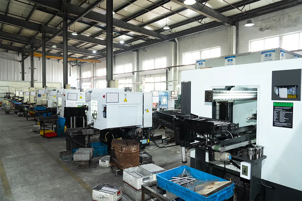
The cylindrical and centerless grinding comparison explains how workholding changes which geometric relationships a process can create. The shaft straightening guide covers the separate question of when bend should be checked and corrected after heat treatment.
A repeatable inspection sequence exposes setup error
An inspector should not start by putting the probe on the feature with the tightest number. First establish whether the datum surfaces are clean, undamaged and capable of creating the intended axis. Then build the rest of the measurement around them.
For a circular runout check, record the axial station rather than writing one result for the entire journal. For total runout, define the sweep length and how the probe travels. On either check, the contact direction and probe orientation must suit the radial or face surface being measured.
A useful report includes the part and drawing revision, characteristic, datum, nominal requirement, actual result, unit, instrument or method, sample quantity and inspection stage. Guanshuo's motor shaft quality inspection guide shows how those fields fit into a wider first-article and batch record.
The indicator pattern is a clue, not a diagnosis
Two parts can show the same TIR and need different corrections. A single high point that repeats at every measured station suggests a different problem from a trace that grows steadily toward one end. Before changing a grinding offset or pressing a shaft straight, look at the pattern and test the setup.
| Observed pattern | Possible causes to investigate | Next check |
|---|---|---|
| One high angular position repeats at several axial stations | Surface axis offset, datum seating error or fixture eccentricity | Mark the high point, reseat the shaft and repeat. Verify datum form and fixture runout. |
| TIR grows toward one end of a long journal | Axis tilt, shaft bend, support position or taper | Measure at defined stations in two planes and check straightness or cylindricity separately. |
| Several peaks appear during one revolution | Lobing, local form error, surface waviness or probe response | Use a roundness or cylindricity method with an agreed filter and sampling strategy. |
| The high point moves after cleaning or reseating | Dirt, burrs, center-hole damage, variable clamping or unstable support | Inspect contact surfaces and repeat with the fixture verified. |
| Geometry passes but the assembled motor still vibrates | Mass imbalance, bearing condition, rotor assembly error, coupling or operating resonance | Continue with assembly, bearing and dynamic balance checks. Do not keep tightening shaft TIR without evidence. |
This table is deliberately diagnostic rather than absolute. An indicator trace cannot identify the root cause on its own. It narrows the next inspection. That distinction prevents an expensive habit we often see in drawing reviews: applying a smaller tolerance to the last surface measured when the datum or fixture created the disagreement.
A good drawing note names the axis, surface, span and stage
A feature control frame under the selected standard is better than a paragraph of shop language. The following checklist shows the information that must survive into the final drawing and control plan. Bracketed fields are placeholders, not Guanshuo capability promises or recommended tolerances.
GOVERNING DRAWING STANDARD: [STANDARD AND EDITION]
FUNCTIONAL DATUM AXIS: [DATUM FEATURE OR COMMON DATUM FEATURES]

CIRCULAR RUNOUT OF [SURFACE] TO [DATUM]: [LIMIT]
MEASUREMENT SECTIONS: [LOCATIONS FROM DATUM FACE]

TOTAL RUNOUT OF [SURFACE] TO [DATUM]: [LIMIT]
CONTROLLED AXIAL SPAN: [START AND END]

STRAIGHTNESS OF [SURFACE LINE OR DERIVED AXIS]: [LIMIT]
CONTROLLED LENGTH: [SPAN]

FINAL CONDITION: [AFTER HEAT TREATMENT / GRINDING / COATING / ASSEMBLY]
INSPECTION METHOD OR DATUM SIMULATION: [AGREED METHOD]
REPORTING AND SAMPLING: [FIRST ARTICLE / BATCH / FULL SCREENING AS AGREED]
Send the mating-part drawing or at least identify the bearing, seal, rotor and coupling interfaces. Mark which journals locate the shaft during operation. If an existing drawing uses concentricity, include the original standard and revision rather than replacing the term before the design intent is understood.
The factory can then choose a process and inspection route that preserves the same axis from machining through final acceptance. Without that chain, a very small number can still describe the wrong geometry.
Frequently asked questions
What is the difference between shaft runout and concentricity?
Runout controls how a surface varies while the shaft rotates about a stated datum axis. Concentricity or coaxiality concerns the location of derived centers or axes under the governing drawing standard. A dial-indicator TIR reading is therefore not automatically a concentricity result.
Is TIR twice the shaft eccentricity?
Only in an ideal case where the measured surface is round and fixture or spindle error is negligible. A real TIR reading can also contain roundness error, waviness, datum-feature form, dirt, burrs and fixture error. Record the measured TIR rather than dividing it by two without proving those other contributions are insignificant.
What is the difference between circular runout and total runout?
Circular runout is evaluated at one circular cross-section during rotation. Total runout evaluates the full controlled surface while the shaft rotates and the probe traverses the stated length. Total runout therefore covers variation along the surface as well as around it.
Can a straight motor shaft still have poor runout?
Yes. Straightness controls the form of a surface line or derived median line without referencing another feature. A straight journal can still sit off-center or at an angle to the datum axis established by the bearing journals, which produces runout during rotation.
What should I send for a motor shaft runout review?
Send the complete drawing with its governing standard and revision, identify the functional bearing or locating journals, mark every controlled surface and axial span, and state whether acceptance applies after heat treatment, grinding, coating or assembly. Include the mating-part information, inspection method and reporting or sampling requirement when they affect the decision.