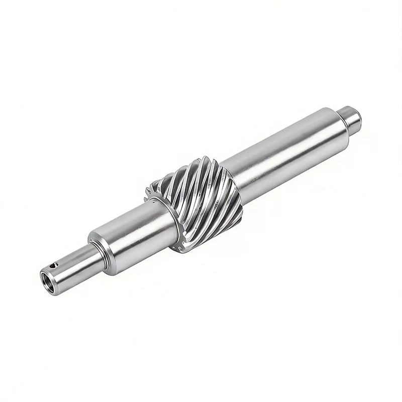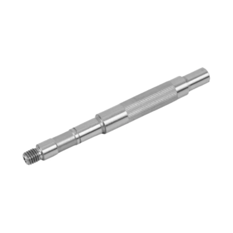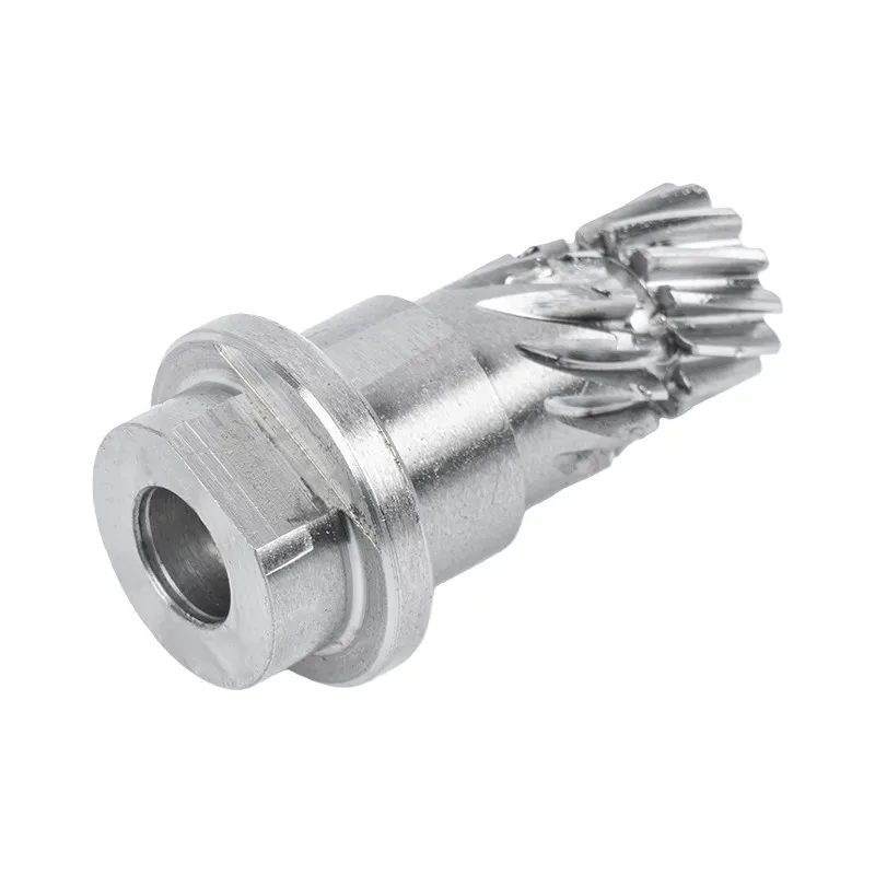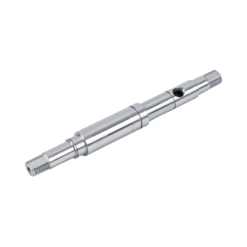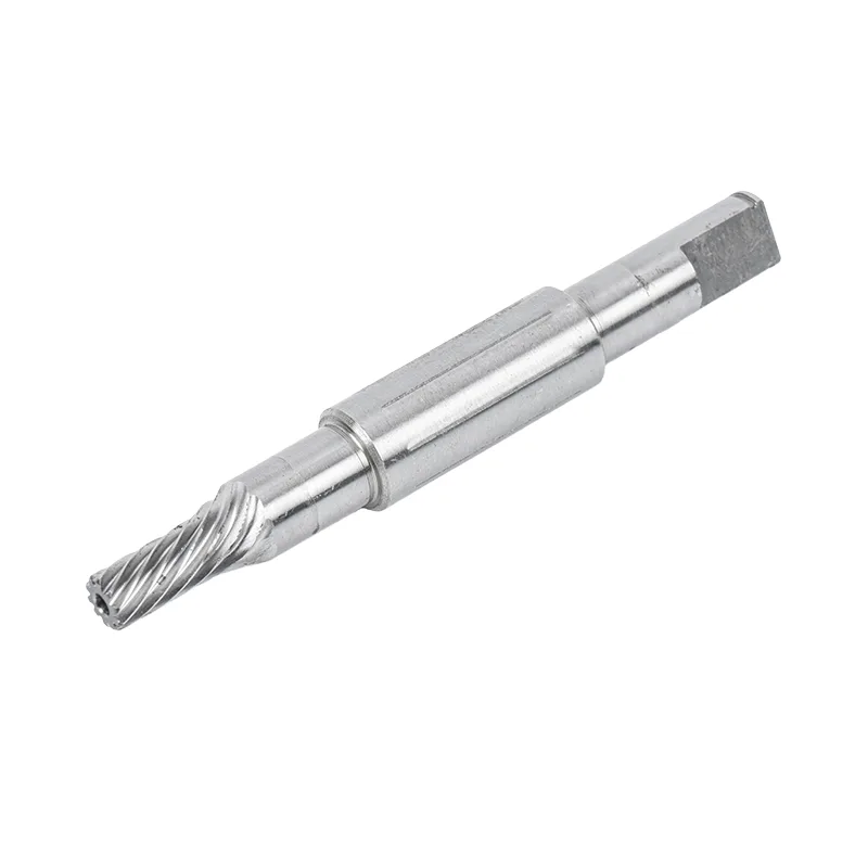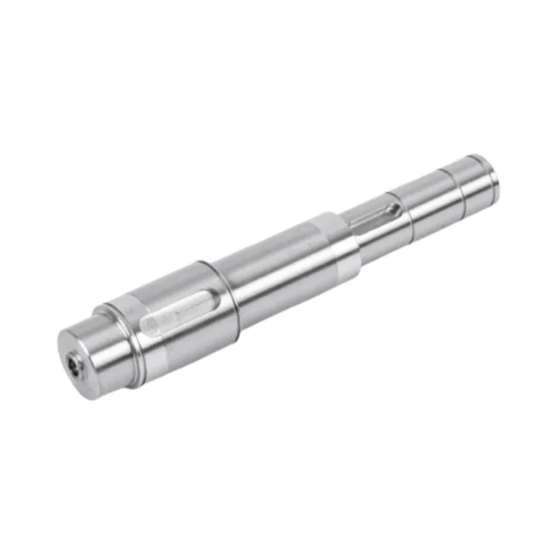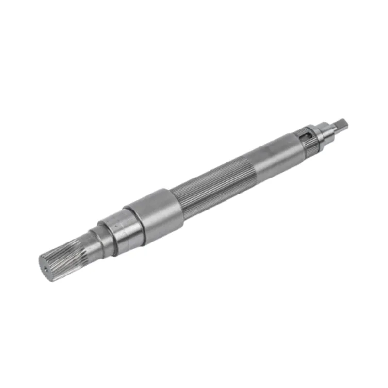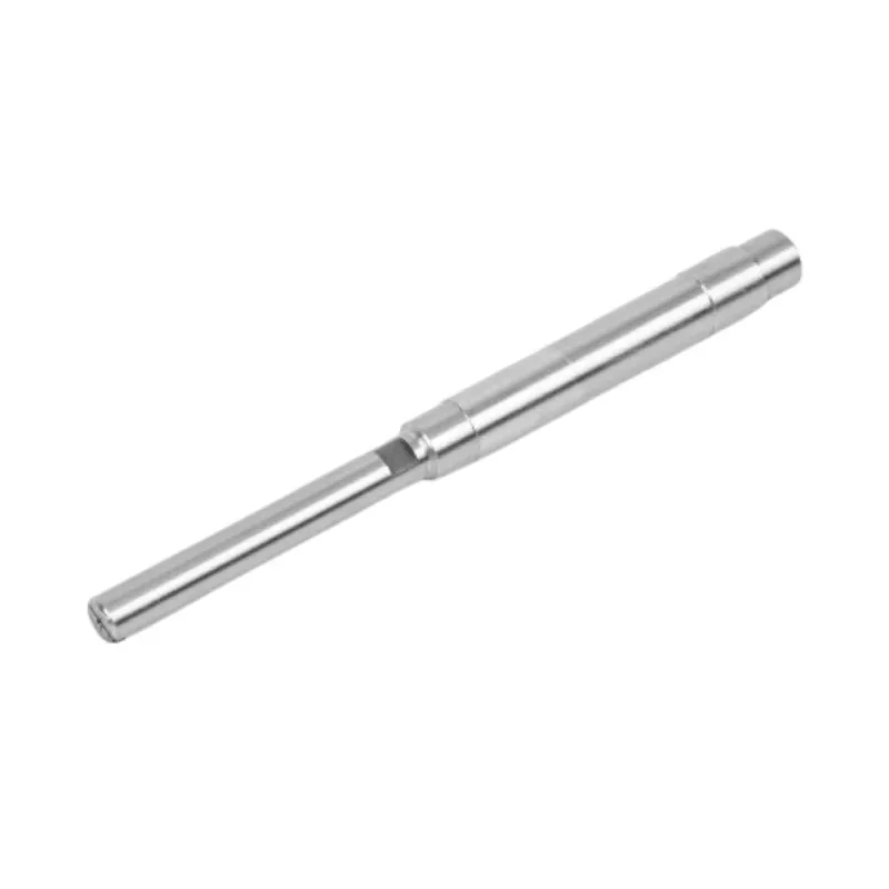

A note that says HRC 55 may look precise, but it leaves the factory with several unanswered questions. Which journal needs that hardness? Is the value required at the finished surface or before grinding? How deep must the hardened zone extend, and what must remain tough underneath?
We see heat treatment as a drawing problem before it becomes a furnace problem. The useful specification connects the material, hardened area, hardness range, layer depth, finishing sequence and test location. If one of those pieces is missing, two suppliers can follow the same short note and deliver different parts.
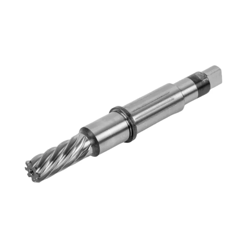
Start with the job the hardened layer must do
Heat treatment is not a finish that can be selected from a menu without looking at the shaft. A bearing journal may need wear resistance. A spline or integral gear may need a hard working surface over a tougher core. Another shaft may need strength through much of its section. These are different jobs, even if the purchase order calls all of them "hardening."
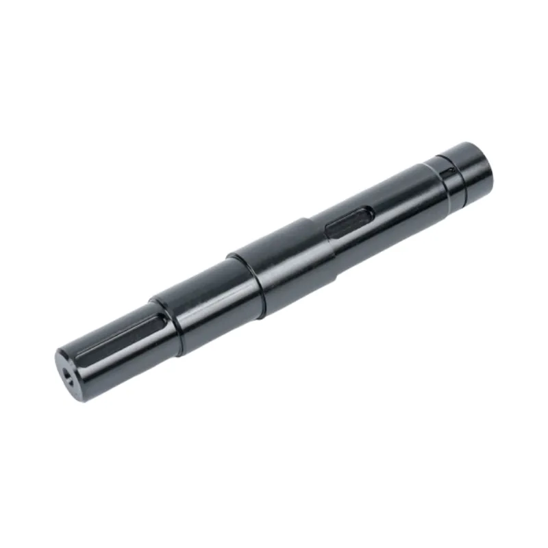
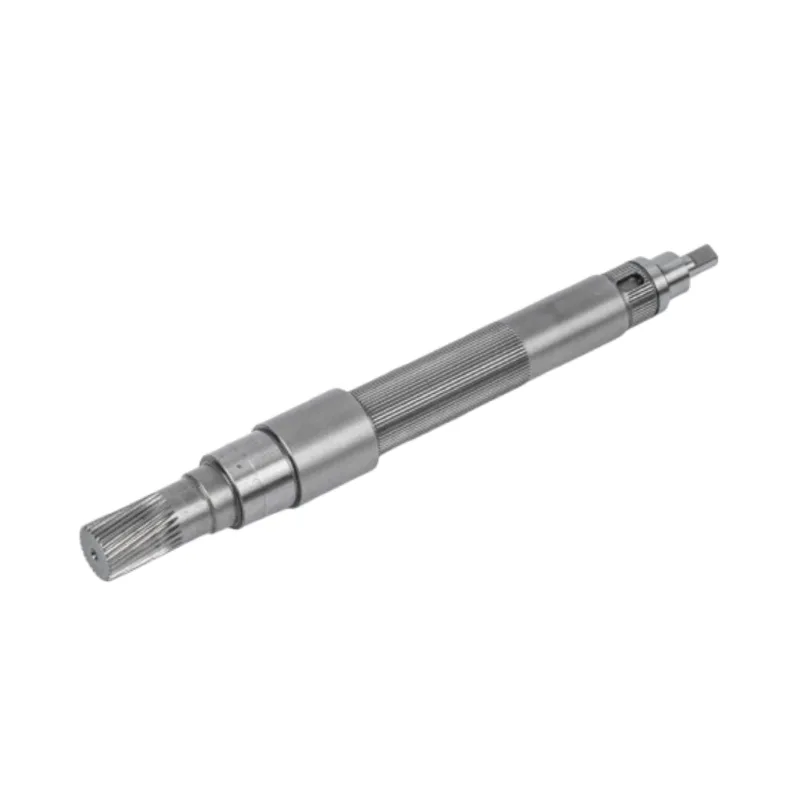
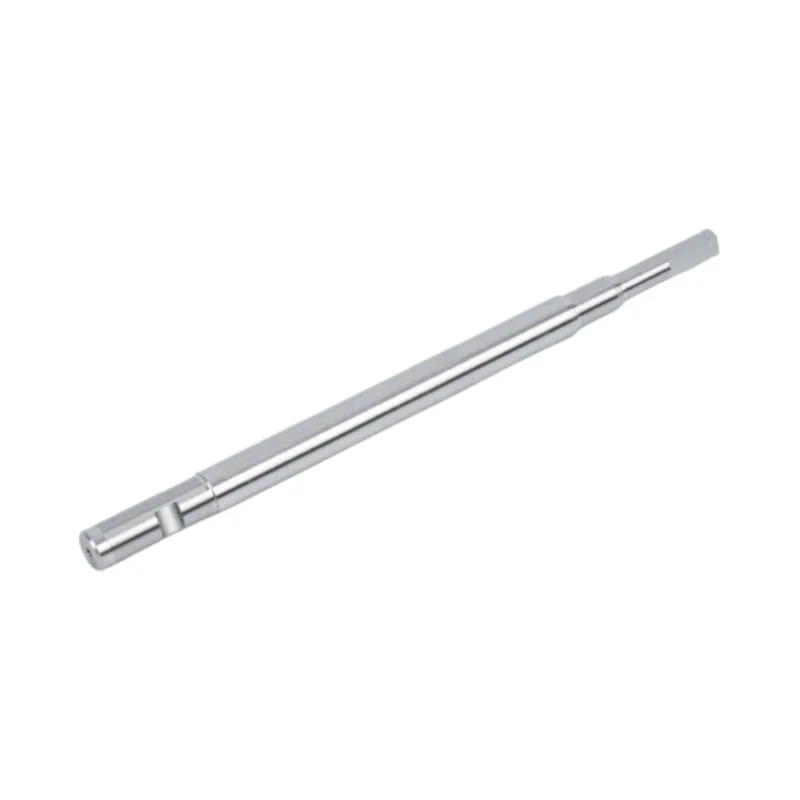
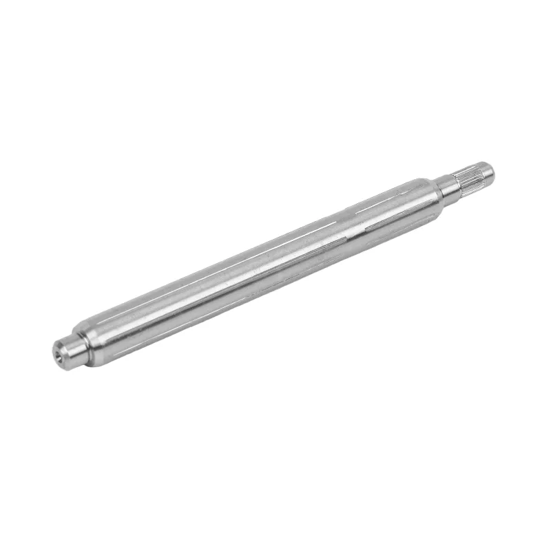
Guanshuo's quenching motor shaft page lists carburizing and quenching, high-frequency surface quenching, and induction hardening. The published conventional range covers 45# steel, 40Cr and 42CrMo, with surface hardness of HRC 45-60 and effective case depth of 0.8-2.0 mm. It also lists Ra 0.4-0.8 μm after fine grinding.
Those figures describe a manufacturing range, not a universal combination. A 45# shaft, a 42CrMo shaft and a carburized component do not receive the same process simply because the requested surface number falls between HRC 45 and 60. Section size, material condition, hardened-zone shape and final machining all affect the route. We confirm them together against the drawing.
| Drawing item | Question it settles | What it cannot prove by itself |
|---|---|---|
| Material grade and starting condition | What steel is being heat treated and its condition before the operation | Final hardness, layer depth or distortion |
| Named process | Whether the design calls for localized surface hardening, carburizing and quenching, or another agreed route | The exact hardened area or acceptance result |
| Surface-hardness range | The allowed hardness at a stated surface and test location | How deep that hardness extends |
| Effective case depth | How far the hardened profile remains above an agreed limiting hardness | Surface finish, part size or core toughness |
| Core-hardness requirement | The allowed hardness away from the hardened layer, if the design needs this control | Surface wear resistance |
| Final dimensional and geometric controls | What the shaft must meet after heat treatment, straightening and grinding | The hardness profile below the surface |
Our factory preference is to ask what is wearing, what is carrying the load and which feature locates the assembly. That answer often narrows the hardening zone. Extending a hardening callout over every shoulder, thread and relief may add distortion risk without helping the part.
A hardness number needs a map
Use hatching, chain lines or a clearly dimensioned band to show where hardening begins and ends. Dimension the boundary from a stable feature. A note such as "harden bearing seat" is less useful when the seat blends into a shoulder or seal track.
If the thread, center hole, keyway end or another feature must remain below a hardness limit for later machining or assembly, mark that area. The transition between hard and soft zones also needs space. Do not make the factory guess whether the boundary may enter a relief or must stop before it.
A surface photo cannot verify this map. Color changes may come from heat treatment, masking, handling or later finishing, and grinding can remove visible evidence. The zone is accepted through the agreed measurement plan, not by appearance.
Surface hardness and effective case depth are two measurements
A surface hardness reading answers what happened at one location near the surface. Effective case depth answers how far the hardness profile remains above a defined limit. One cannot replace the other.
The current ISO 18203:2026 standard covers methods for measuring case hardening depth, surface hardening depth, nitriding hardness depth and total thickness of surface-hardened layers. Write the depth type and the governing method on the drawing. The phrase case depth 1.0 mm is incomplete if the buyer and manufacturer use different depth definitions.
Rockwell hardness testing, such as ASTM E18, is useful for acceptance testing at a specified location. The standard itself warns that one location may not represent the whole part. A Vickers or Knoop microindentation method, such as ASTM E384, can measure changes over a small distance and is suited to a hardness traverse on a prepared cross-section.
A cross-section test is destructive. Decide during quotation whether the evidence will come from a sacrificial production part, an agreed process-control specimen or another approved plan. The sample location matters on a stepped shaft because section thickness and hardening boundaries change along its length.
| Ambiguous note | What is missing | More useful direction |
|---|---|---|
| Harden to HRC 55 | Range, zone, location, process and final condition | Give the permitted range, mark the zone, identify the test point and state whether the result applies after final grinding. |
| Case depth 1 mm | Depth type, limiting hardness, tolerance and test method | State effective or total depth, the required limits, governing standard or agreed definition, and cross-section location. |
| Induction harden journal | Journal boundaries and transition-zone treatment | Dimension the start and end positions from a datum and mark any must-remain-soft area. |
| Check hardness | Scale, load, quantity, location and report content | Identify the test method, exact locations, sampling plan and required recorded results. |
The finished surface is the surface the motor receives
Heat treatment can move a shaft, while hardening and quenching leave the journals unfinished. Precision shafts therefore need a route that protects both metallurgy and geometry. Guanshuo's process places heat treatment before straightening and final grinding. Its separate shaft straightening guide explains why the hardened blank is measured and corrected before the running diameters reach final size.
Grinding removes material from the hardened layer. If case depth is inspected before grinding but the drawing requires it on the finished journal, the report and the part are describing different surfaces.
This is also why diameter stock and radial stock must not be confused. A drawing or routing that says "leave 0.20 mm for grinding" should clarify whether that means 0.20 mm on diameter or 0.20 mm per side. The difference changes how much hardened material remains.
Do not chase final size with unrestricted grinding. Excess removal may produce a correct diameter with too little case depth. The drawing must make both requirements visible so production and inspection cannot trade one away for the other.
Plan heat treatment and precision machining as one route
The exact route changes with material and geometry, but the responsibilities of each stage stay clear. Rough machining creates the form and preserves finishing stock. Heat treatment creates the metallurgical condition. Straightening deals with movement where required. Grinding creates the final running surfaces. Inspection checks the part in its delivery condition.
| Stage | Heat-treatment question | Evidence or control |
|---|---|---|
| Material receipt | Is the steel grade and starting condition the one approved on the drawing? | Material identification and agreed traceability record |
| Rough and semi-finish machining | Are the hardening zones accessible, and is enough finishing stock reserved? | Pre-heat-treatment dimensions and stock plan |
| Heat treatment | Did the designated zones receive the approved process? | Lot and process record, plus the agreed hardness checks |
| Straightening | Has movement been corrected without losing the later grinding allowance? | Intermediate geometry check when the route requires it |
| Final grinding | Do the finished journals meet size and roughness while retaining the required hardened layer? | Final diameter, geometry, roughness and post-grind hardness or depth evidence |
| Final inspection | Does the delivered part meet the drawing revision in the stated condition? | Part-linked inspection report and any destructive-test report required by the plan |
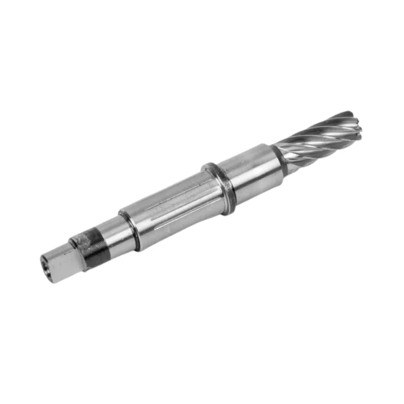

For bearing and seal journals, the surface roughness requirement belongs to the final ground surface. Hardness and roughness are different acceptance characteristics. A roughness result cannot prove hardness, and a hardness reading cannot show whether the seal track was ground to its specified texture.
Ask for measurements that trace back to the drawing
A heat-treatment certificate that lists one hardness number and a batch date may be adequate for a simple through-hardened blank. It is weak evidence for a stepped shaft with two local hardened bands and a depth requirement.
The report should identify the part number, drawing revision, lot and material. Each result then needs a measurement location, method, scale or load, requirement and actual value. For a hardness traverse, retain the values at their depths and the derived intersection with the specified limiting hardness. A colored macrograph can support the record, but it should not silently replace a hardness-based depth definition.
Guanshuo lists hardness testers and other dimensional and geometric inspection equipment. The broader motor shaft inspection guide explains how the final report ties characteristics to the drawing. For heat treatment, add the zone and production stage so a number cannot drift away from the feature it represents.
- Identify the tested part or approved process-control specimen and the production lot it represents.
- Mark the hardness-test points and destructive cross-section on the shaft drawing.
- Record the hardness method, scale or load and the actual values instead of a simple pass/fail.
- State whether results were taken before or after tempering, straightening and final grinding.
- Keep final diameter, runout or straightness, surface roughness and hardness evidence under the same drawing revision.
A complete drawing note is short because the picture carries the geometry
The values below are a formatting example, not a default specification. A designer must choose the material, process, limits and test standard for the actual load and wear condition.
INDUCTION HARDEN SHADED JOURNALS A AND B ONLY.
FINAL SURFACE HARDNESS: [MIN-MAX HRC], TEST AT LOCATIONS H1 AND H2 AFTER FINAL GRIND.
EFFECTIVE HARDENED DEPTH: [MIN-MAX mm] TO [AGREED LIMITING HARDNESS], AFTER FINAL GRIND.
VERIFY DEPTH AT SECTION C-C USING [GOVERNING STANDARD / AGREED METHOD].
UNSHADED MUST-REMAIN-SOFT ZONES: [LIMIT AND TEST LOCATION, IF REQUIRED].
FINAL JOURNAL SIZE, RUNOUT, STRAIGHTNESS AND Ra: SEE DIMENSIONED DRAWING.
SAMPLING AND REPORT: [APPROVED CONTROL PLAN].
If the contract invokes ISO 18203:2026, ASTM E18 or ASTM E384, name the exact edition required by the customer's quality system. A standard reference should remove ambiguity, not act as decoration.
Send the complete section view rather than an isolated heat-treatment note. Include mating features and explain which surface wears or carries load. Guanshuo currently lists HRC 45-60 surface hardness, 0.8-2.0 mm effective case depth and Ra 0.4-0.8 μm fine-ground surfaces for its conventional quenching shaft range. A drawing review is still required to confirm which combination fits the material, geometry and inspection plan.
Frequently asked questions
Is surface hardness the same as effective case depth?
No. Surface hardness is measured at a specified location near the surface. Effective case depth is the distance from the surface to the point where a hardness profile reaches an agreed limiting hardness. A shaft can pass a surface reading without proving that the hardened layer is deep enough.
Should case depth be specified before or after grinding?
Specify it for the condition that matters in service, which is normally the final ground surface. Grinding removes material from the hardened layer. If a pre-grind test is used for process control, the plan must show how it protects the minimum depth required after grinding.
What hardness and case-depth range does Guanshuo list for quenching motor shafts?
Guanshuo's current quenching motor shaft page lists HRC 45-60 surface hardness and 0.8-2.0 mm effective case depth as conventional adjustable capabilities. The actual combination must be reviewed with the material, shaft size, hardened-zone geometry, finishing stock and inspection method.
Does an HRC reading prove that the whole hardened zone is correct?
No. One HRC result describes its test location. A zone with boundaries or a depth requirement needs an inspection plan that covers those features. A cross-section hardness traverse may be required to verify the depth profile.
What should I send for a heat-treated motor shaft quotation?
Send the complete drawing with material and starting condition, marked hardened zones, process, final surface-hardness range, case-depth definition and limits, must-remain-soft areas, final grinding requirements, geometric tolerances, sampling plan and required report. Include the shaft's load and wear function when it affects the review.