
1. The Industrial Robot Motor Shaft as the Mechanical Backbone of Robotic Motion
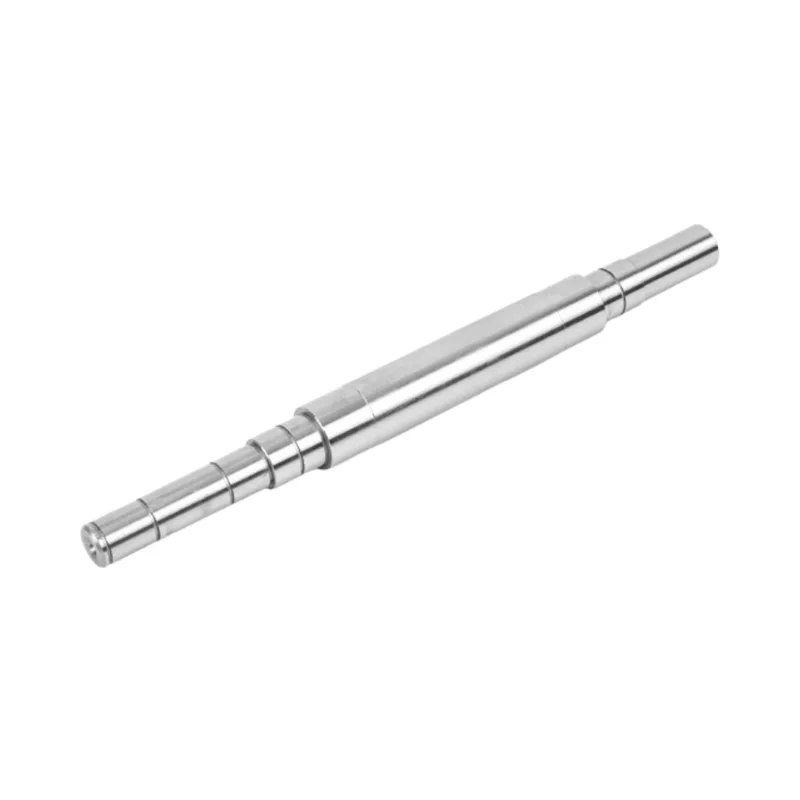
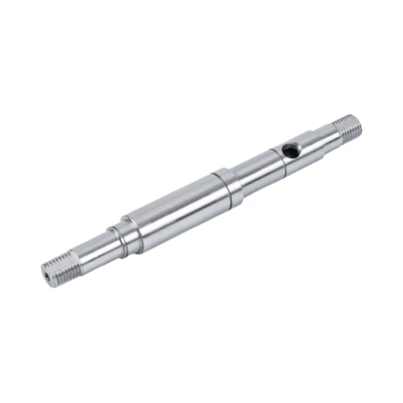
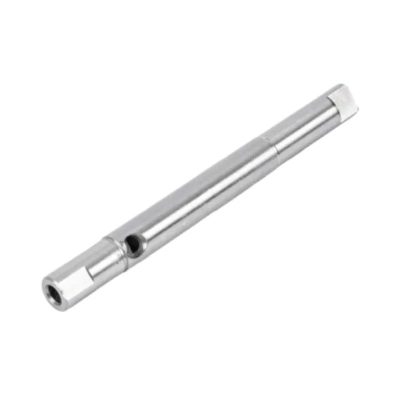
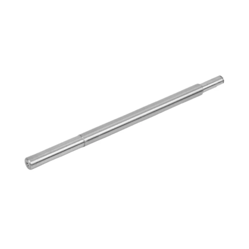
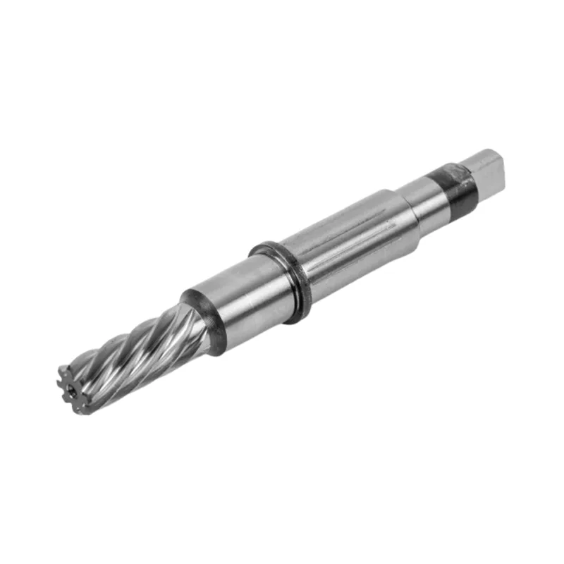
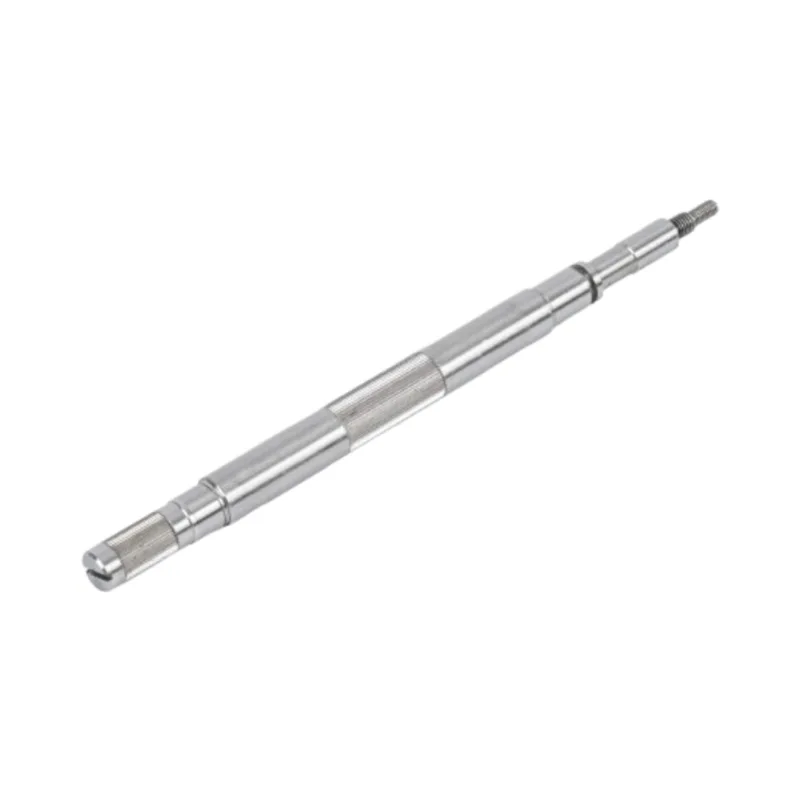
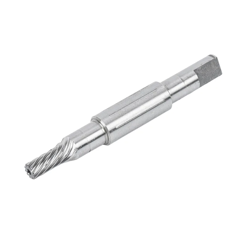
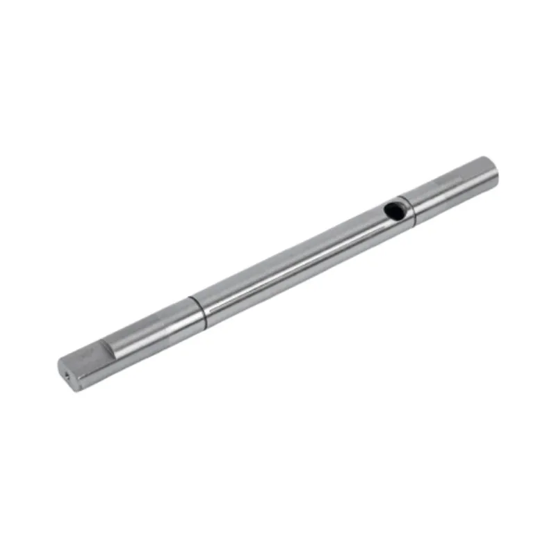
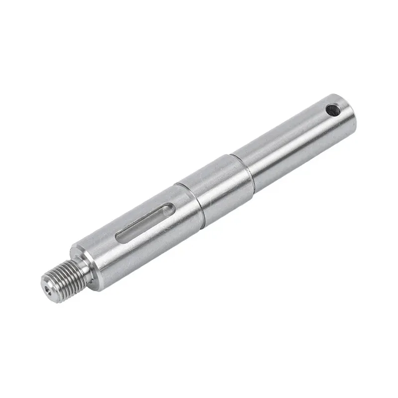
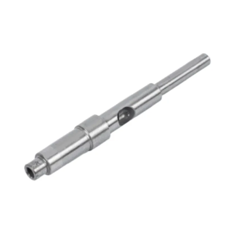
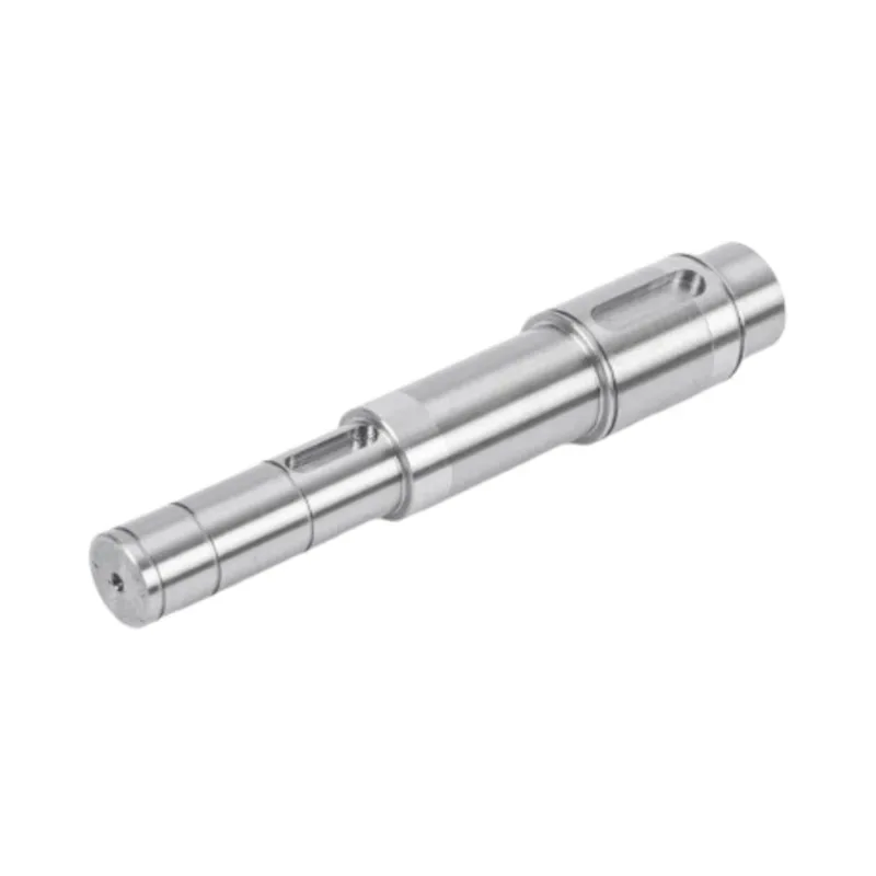
Every industrial robot — from six‑axis articulated arms to SCARA selectors and collaborative cobots — depends on a fundamental mechanical interface between the servo motor and the driven load: the Industrial Robot Motor Shaft. This cylindrical element transmits rotational power from the motor to the gearbox, harmonic drive, or direct joint, converting electromagnetic torque into controlled mechanical displacement. Without a meticulously engineered motor shaft, even the most advanced control algorithms cannot deliver the positional accuracy, repeatability, or dynamic responsiveness that modern production lines require.
The motor shaft in a robotic application encounters a distinct set of operational stresses. It must withstand rapid acceleration and deceleration, frequent start‑stop cycles, variable torque loads, and occasionally harsh environmental conditions — all while preserving sub‑micron positional fidelity. Unlike shafts in general‑purpose machinery, robotic motor shafts operate within closed‑loop servo systems where any backlash, torsional wind‑up, or radial run‑out directly compromises the end‑effector's trajectory. This imposes extraordinary demands on the shaft's geometric precision, material integrity, and surface quality.
In essence, the Industrial Robot Motor Shaft is far more than a simple rotating rod; it is a precision interface that couples the motor's electromagnetic output to the robot's mechanical output. Its performance influences energy efficiency, thermal dissipation, vibration signature, and ultimately the entire drive train's service life. A thorough understanding of this component's engineering is therefore indispensable for robotic system designers, maintenance engineers, and procurement specialists.
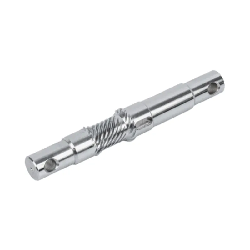
2. Core Design Principles for High-Performance Motor Shafts
Designing a motor shaft for industrial robotics starts with a clear grasp of the application's mechanical requirements. Unlike standard power‑transmission shafts, robotic motor shafts must satisfy a stringent set of criteria that balance strength, stiffness, weight, and dynamic behavior.
2.1 Torque Transmission and Torsional Stiffness
The primary duty of any motor shaft is torque transmission. In robotic joints, the shaft must convey the motor's rated torque — and occasional peak overload torque — without excessive angular deflection. Torsional stiffness, defined as the ratio of applied torque to angular twist, is a critical parameter. Low torsional stiffness introduces compliance into the servo loop, reducing control bandwidth and impairing the robot's ability to reject external disturbances. High‑stiffness shafts ensure that the motor's commanded position transfers faithfully to the joint output, enabling precise path tracking.
Engineers determine the required shaft diameter based on maximum shear stress and permissible angle of twist per unit length. For robotic applications with cycle times measured in fractions of a second, the shaft's polar moment of inertia must also be optimized to minimize reflected inertia at the motor — a factor that directly affects acceleration capability and energy consumption. Hollow shafts, which offer a higher torsional stiffness‑to‑weight ratio, are sometimes adopted in collaborative robots to reduce weight while maintaining adequate torque capacity.
2.2 Dynamic Balancing and Critical Speed
Robotic motors frequently operate at high rotational speeds, especially in high‑speed pick‑and‑place or assembly tasks. Under such conditions, even minor mass imbalances in the motor shaft generate centrifugal forces that excite vibrations, increase bearing loads, and produce audible noise. Dynamic balancing — performed on precision balancing machines — ensures that the shaft's mass axis coincides with its rotational axis within tight tolerances, often to ISO 1940 grade G2.5 or better.
Additionally, the shaft's critical speed — the rotational speed at which natural bending frequencies are excited — must be well above the maximum operating speed. This requires careful selection of the shaft's length‑to‑diameter ratio, support bearing spacing, and material damping properties. Designers often use finite element analysis to predict mode shapes and adjust geometry to avoid resonance, thereby ensuring smooth operation across the entire speed range.
3. Material Selection — The Foundation of Reliability
The choice of material for a Industrial Robot Motor Shaft is arguably the most consequential decision in the entire engineering process. Material properties determine the shaft's strength, fatigue life, wear resistance, corrosion resistance, and dimensional stability under thermal cycling.
3.1 Alloy Steels and Stainless Grades
Most industrial robot motor shafts are manufactured from medium‑carbon alloy steels such as 40Cr, 42CrMo4, or equivalent grades. These materials offer an excellent combination of tensile strength, toughness, and machinability. For applications demanding superior corrosion resistance — such as food‑grade robots or those operating in wash‑down environments — stainless steels like SUS420 or 440C are preferred. Stainless shafts provide adequate hardness after heat treatment while resisting oxidation and chemical attack.
High‑performance shafts may also incorporate surface treatments such as nitriding, carburizing, or induction hardening to create a wear‑resistant case while retaining a tough, ductile core. This case‑core architecture is particularly valuable in robotic joints where the shaft interfaces with bearings, seals, or spline couplings that impose concentrated contact stresses.
3.2 Heat Treatment and Surface Hardening
Heat treatment transforms the raw material's microstructure to achieve the desired mechanical properties. Quenching and tempering produce a uniform martensitic structure with high yield strength and good fracture toughness. For shafts that experience rolling contact fatigue — such as those supporting radial loads through bearings — surface hardness of 55–62 HRC is typically specified to resist pitting and spalling.
It is important to note that excessive hardness can reduce toughness and increase susceptibility to brittle fracture under shock loading. Therefore, the heat treatment process must be carefully controlled to achieve the optimal balance between surface durability and core resilience — a balance that experienced manufacturers refine through decades of process optimization.
4. Manufacturing Processes That Shape Precision
Translating a material billet into a finished motor shaft that meets sub‑micron tolerances requires a multi‑stage manufacturing process, each stage contributing to the final geometric and surface quality.
4.1 CNC Turning and Grinding
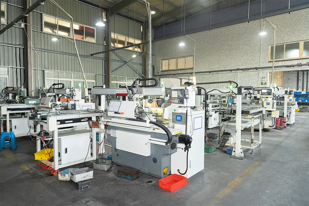
The manufacturing journey typically begins with CNC turning, where the raw bar stock is machined to near‑net shape, creating stepped diameters, shoulders, threads, and keyways. Modern CNC lathes equipped with live tooling can perform milling and drilling operations in a single setup, reducing cumulative positioning errors.
Following turning, the shaft undergoes precision grinding — either centerless or cylindrical — to achieve the final dimensional tolerances and surface finish. Grinding removes the last few hundredths of a millimeter of material, producing surfaces with roughness values (Ra) as low as 0.2–0.4 µm. This level of finish is essential for proper bearing fit, seal performance, and reduced friction during operation.
For shafts with splines, gear teeth, or other complex features, additional operations such as hobbing, shaping, or broaching may be employed. Each operation introduces its own set of tolerances that must be managed within the overall dimensional budget.
4.2 Quality Control and Metrology
Quality assurance in motor shaft manufacturing relies on a combination of in‑process gauging and final inspection using coordinate measuring machines (CMM), optical comparators, and surface profilometers. Key measurements include:
- Diameter at critical bearing journals (typically controlled to ±0.005 mm or tighter)
- Concentricity between multiple diameters
- Straightness and cylindricity
- Surface roughness and waviness
- Hardness profile from surface to core
Advanced manufacturers also employ non‑destructive testing methods such as magnetic particle inspection or eddy current testing to detect subsurface defects that could compromise fatigue strength. Every shaft that passes these rigorous checks earns the right to be installed in a robot that will perform millions of cycles over its service life.
5. Tolerances, Surface Finish, and Geometric Integrity
The Industrial Robot Motor Shaft operates in a world measured in microns. The tolerances applied to its critical features directly determine the robot's positional accuracy, repeatability, and long‑term reliability.
For bearing journals, typical diameter tolerances range from ±0.005 mm to ±0.010 mm, depending on the bearing type and fit class. Tighter tolerances — as low as ±0.002 mm — are specified for ultra‑precision applications such as semiconductor handling robots or medical robotics. Concentricity between journals is often held to 0.01 mm or less to prevent radial run‑out that would induce vibration and reduce bearing life.
Surface finish is equally critical. A rough shaft surface increases friction, accelerates seal wear, and provides nucleation sites for fatigue cracks. For robotic motor shafts, a surface finish of Ra 0.4 µm or better is standard, with some applications calling for Ra 0.2 µm on sealing surfaces. Achieving such finishes requires not only skilled grinding but also careful control of grinding wheel grit, coolant, and feed rates.
Geometric tolerances — including straightness, roundness, and cylindricity — ensure that the shaft remains within its intended envelope as it rotates. Any deviation from perfect geometry translates into cyclic loading on bearings and seals, ultimately shortening the robot's maintenance interval. The cumulative effect of these tolerances is that a properly manufactured motor shaft enables the robot to achieve its rated repeatability — often ±0.02 mm or better — over its entire working envelope.
6. Failure Modes and Preventive Strategies
Even the best‑engineered motor shaft can fail if subjected to conditions beyond its design limits. Understanding common failure modes helps designers and maintenance engineers implement preventive measures that extend shaft life and reduce unplanned downtime.
Fatigue fracture is the most common failure mechanism in rotating shafts. Repeated cyclic bending or torsional stresses, often exacerbated by stress concentrations at keyways, shoulders, or press‑fit interfaces, initiate cracks that propagate until final rupture. Preventive strategies include generous fillet radii, surface shot‑peening to induce compressive residual stresses, and careful control of operating loads to avoid exceeding the endurance limit.
Wear and fretting occur at interfaces where the shaft contacts bearings, seals, or couplings. Micromotion under load can produce abrasive debris that accelerates material loss and degrades fit. Hard surface coatings, proper lubrication, and maintaining correct interference fits are effective countermeasures.
Bending or deflection under excessive radial loads can cause the shaft to contact stationary components or induce misalignment in the drive train. This is particularly relevant in robots with long, cantilevered arms where the motor shaft may support overhung loads. Increasing shaft diameter, using higher‑strength materials, or relocating bearings closer to the load point can mitigate this risk.
Corrosion and pitting affect shafts operating in humid, chemically aggressive, or wash‑down environments. Stainless steel grades, protective coatings such as zinc plating or electroless nickel, and regular cleaning protocols help preserve the shaft's surface integrity.
Regular condition monitoring — including vibration analysis, temperature monitoring, and periodic dimensional inspection — allows early detection of developing faults, enabling corrective action before catastrophic failure occurs. This proactive approach is the hallmark of world‑class robotic maintenance programs.
7. Frequently Asked Questions
Looking for a trusted partner for your robotic drivetrain components?
Guanshuo combines decades of precision manufacturing expertise with advanced CNC and grinding capabilities to produce motor shafts that meet the most demanding robotic applications.
From material selection and heat treatment to final inspection, every shaft is engineered for performance, durability, and consistency.
Contact us to discuss your requirements